Steerable spine implant insertion device and method

a technology of implant insertion device and spine, which is applied in the field of medical devices, can solve the problems of destabilizing the spinal column, pain and nerve damage, and altering the natural separation distance between adjacent vertebrae,

Inactive Publication Date: 2008-06-12
G&L CONSULTING
View PDF61 Cites 244 Cited by
  • Summary
  • Abstract
  • Description
  • Claims
  • Application Information

AI Technical Summary

Problems solved by technology

Partial or full removal of an intervertebral disc may destabilize the spinal column.
Destabilization of a spinal column may result in alteration of a natural separation distance between adjacent vertebra.
Excessive pressure applied to the nerves may cause pain and nerve damage.

Method used


Image

  • Steerable spine implant insertion device and method
  • Steerable spine implant insertion device and method
  • Steerable spine implant insertion device and method

Examples


Embodiment Construction

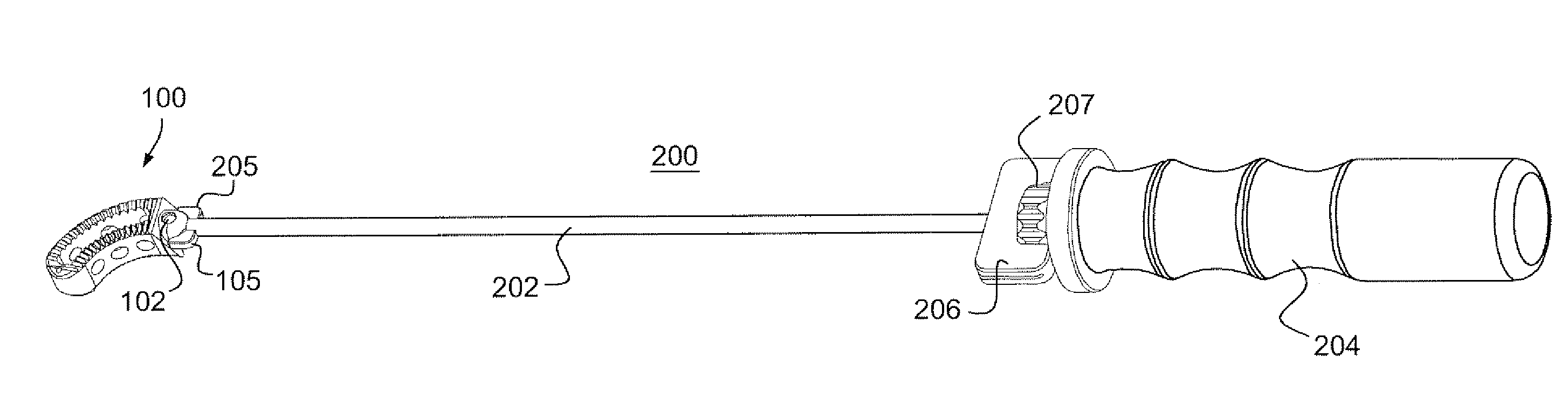
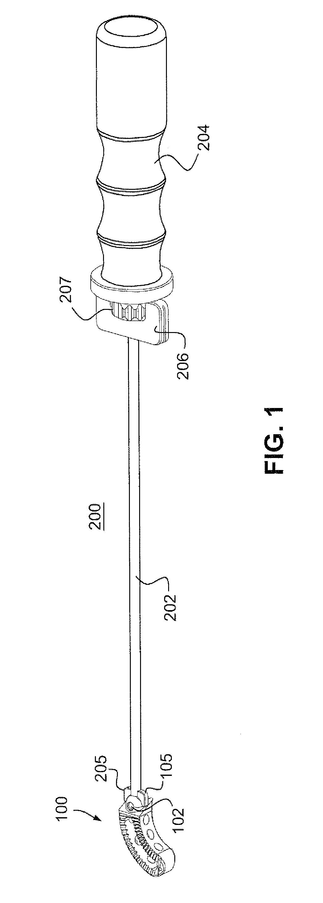
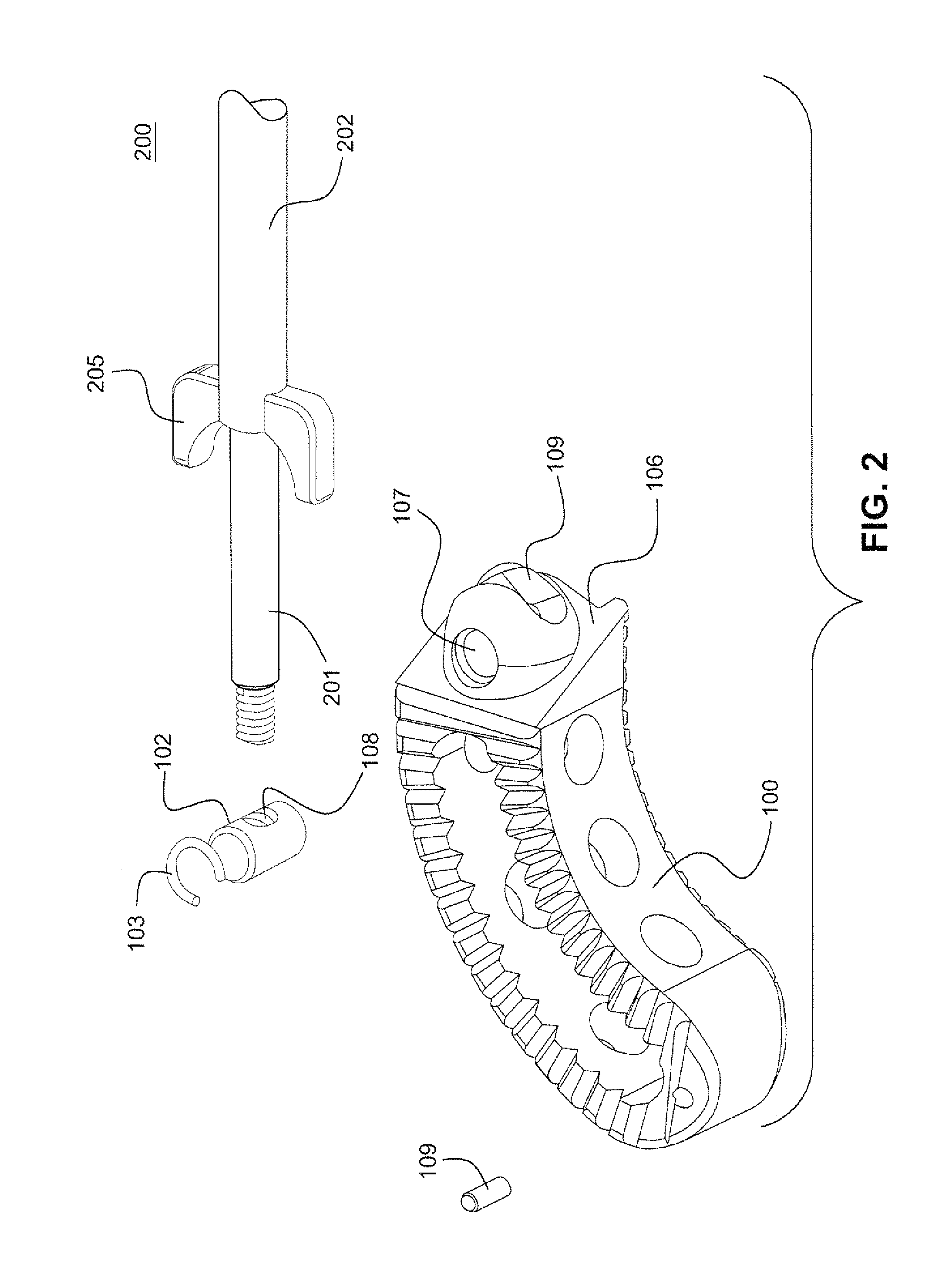
[0022]FIG. 1 shows the spinal implant 100 releasably attached to an insertion instrument 200. The implant 100 may be made by made of PEEK plastic commonly used in spinal implants. The implant includes a hemispherical mount 105 and slanted cam surface 106 from which the mount protrudes. The tip of rod 201 pivotably attaches to the mount such that the implant may pivot with respect to the axis of the instrument. The pivoting of the implant is controlled by the knob on the instrument that rotates the cam wings 205 about the hemispherical surface. The rotation of the cam, slides the front edges of the cam wings across the cam surface 106 and thereby forces the implant to pivot with respect to the axis of the instrument.

[0023]A knob (e.g. actuator wings) 206 on the on the proximal end of the instrument enables a surgeon to rotate the cam and thereby adjust the angle between the implant and the axis of the instrument. Pivoting of the implant is caused as the actuator pushers 205 (e.g., ca...


PUM


Abstract

A method to insert a spinal implant into a vertebral space, the method including the steps of: grasping the implant with a distal end of an implant insertion tool; holding a proximal end of the implant insertion tool and inserting the implant toward the vertebral space; and manipulating the proximal end to apply a yaw movement to the implant while the implant is attached to the tool and in the vertebral space.

Description

[0001]This application claims the benefit of the filing date of U.S. Provisional Patent Application Ser. No. 60 / 869,473, filed on Dec. 11, 2006, the entirety of which is incorporated by reference.BACKGROUND OF THE INVENTION[0002]The present invention generally relates to the field of medical devices. Some embodiments of the invention relate to spinal implants inserted in the spine of a patient during surgical procedures and to instruments used to insert the implants. Other embodiments of the invention relate to methods for positioning, rotating and advancing an implant during a surgical procedure.[0003]A spinal implant may be used to stabilize a portion of a spine. The implant may promote bone growth between adjacent vertebra that fuses the vertebra together. The implant may include a spherical protrusion, a threaded pin and an angled surface to facilitate remote adjustment of the implant position using an insertion instrument.[0004]The insertion instrument may include, but is not l...

Claims


Application Information

Patent Timeline
Patent Type & Authority Applications(United States)
IPC IPC(8): A61B17/58A61B17/00
CPCA61F2/4465A61F2/4611A61F2002/30133A61F2002/30523A61F2002/30538A61F2250/0006A61F2002/4622A61F2002/4627A61F2002/4629A61F2220/0025A61F2230/0015A61F2002/30904
Inventor GATELY, NICHOLAS V.GELFAND, MARK
Owner G&L CONSULTING
Why Eureka
Try Eureka