Network control system, network control method, and computer product
- Summary
- Abstract
- Description
- Claims
- Application Information
AI Technical Summary
Benefits of technology
Problems solved by technology
Method used
Image
Examples
first embodiment
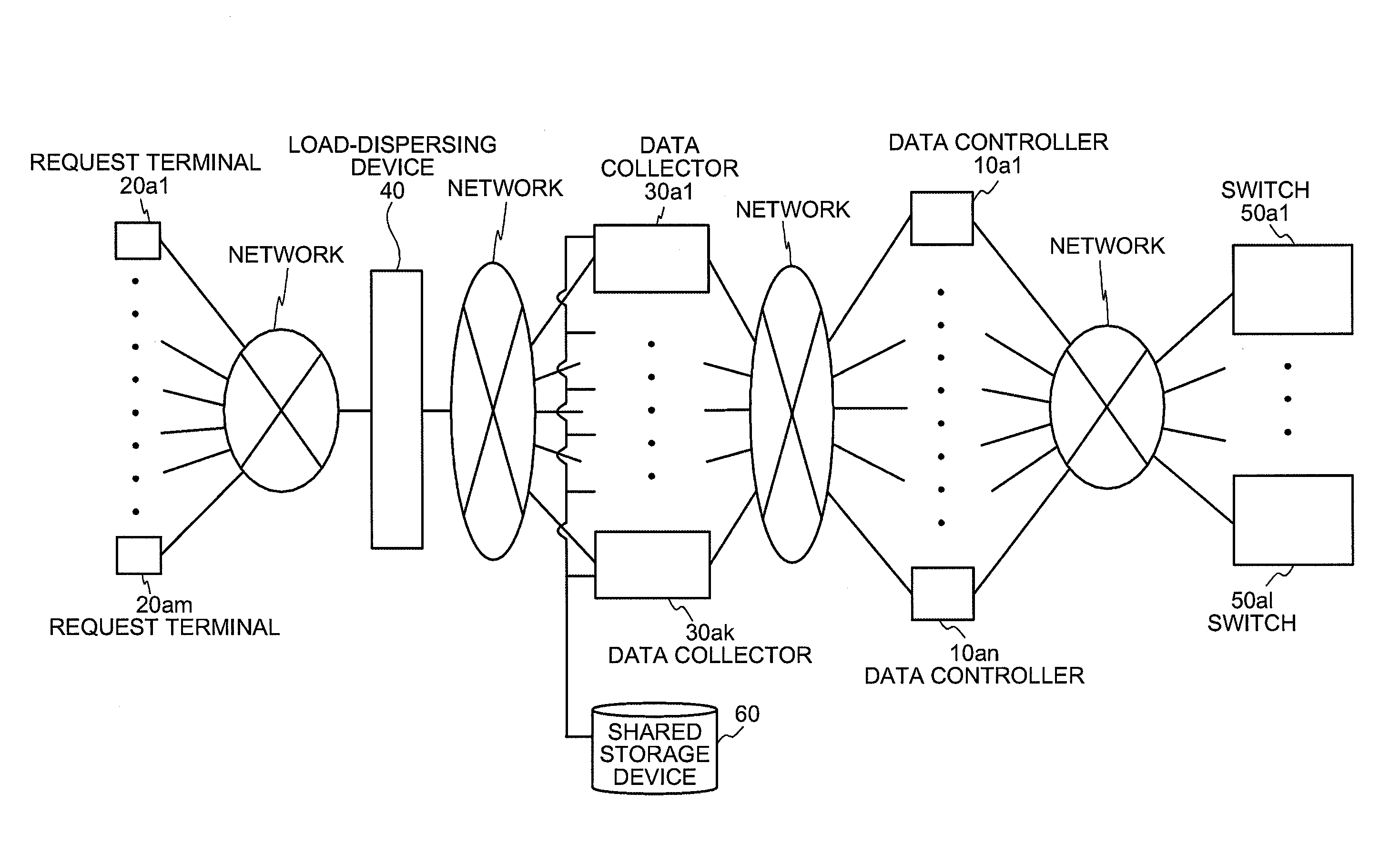
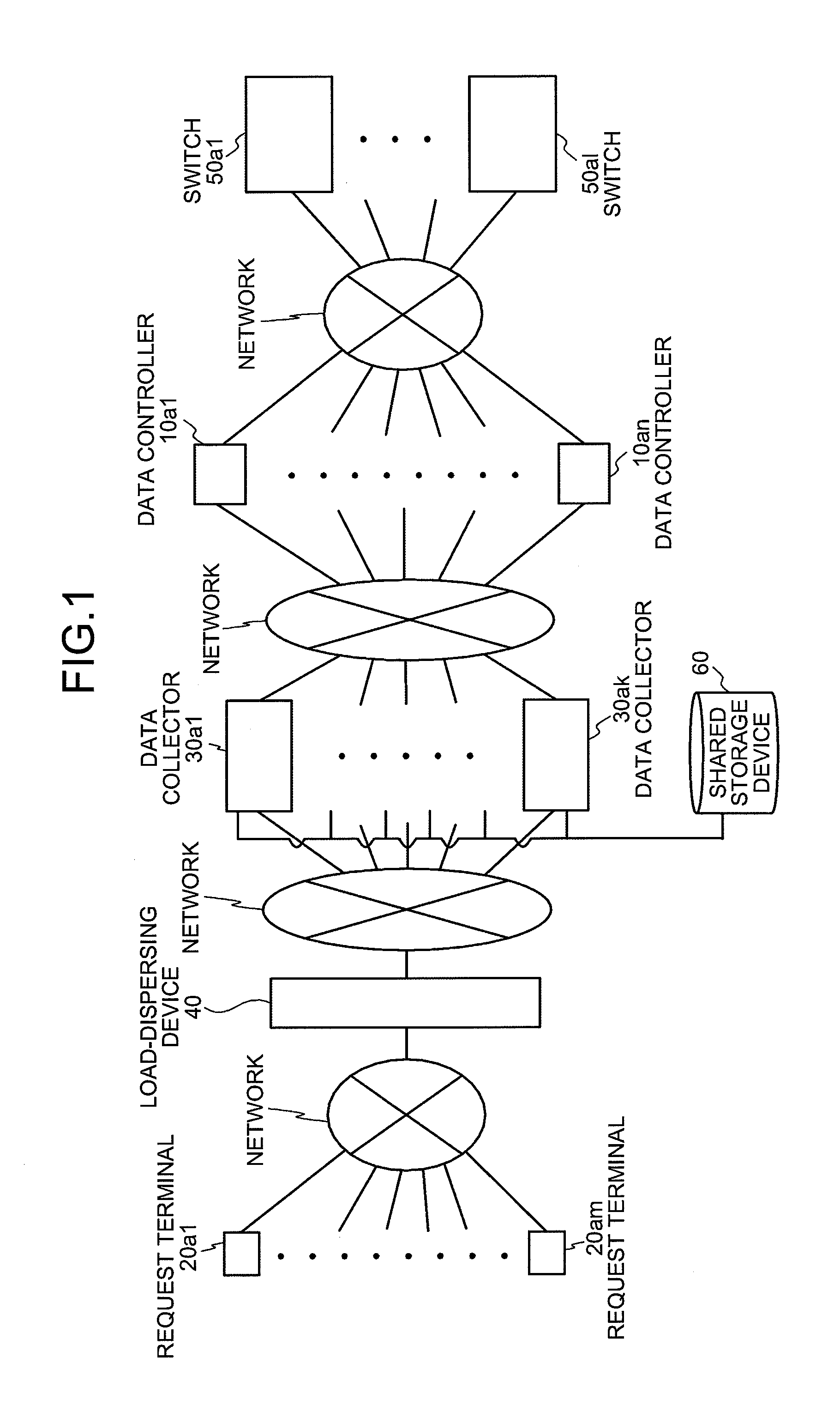
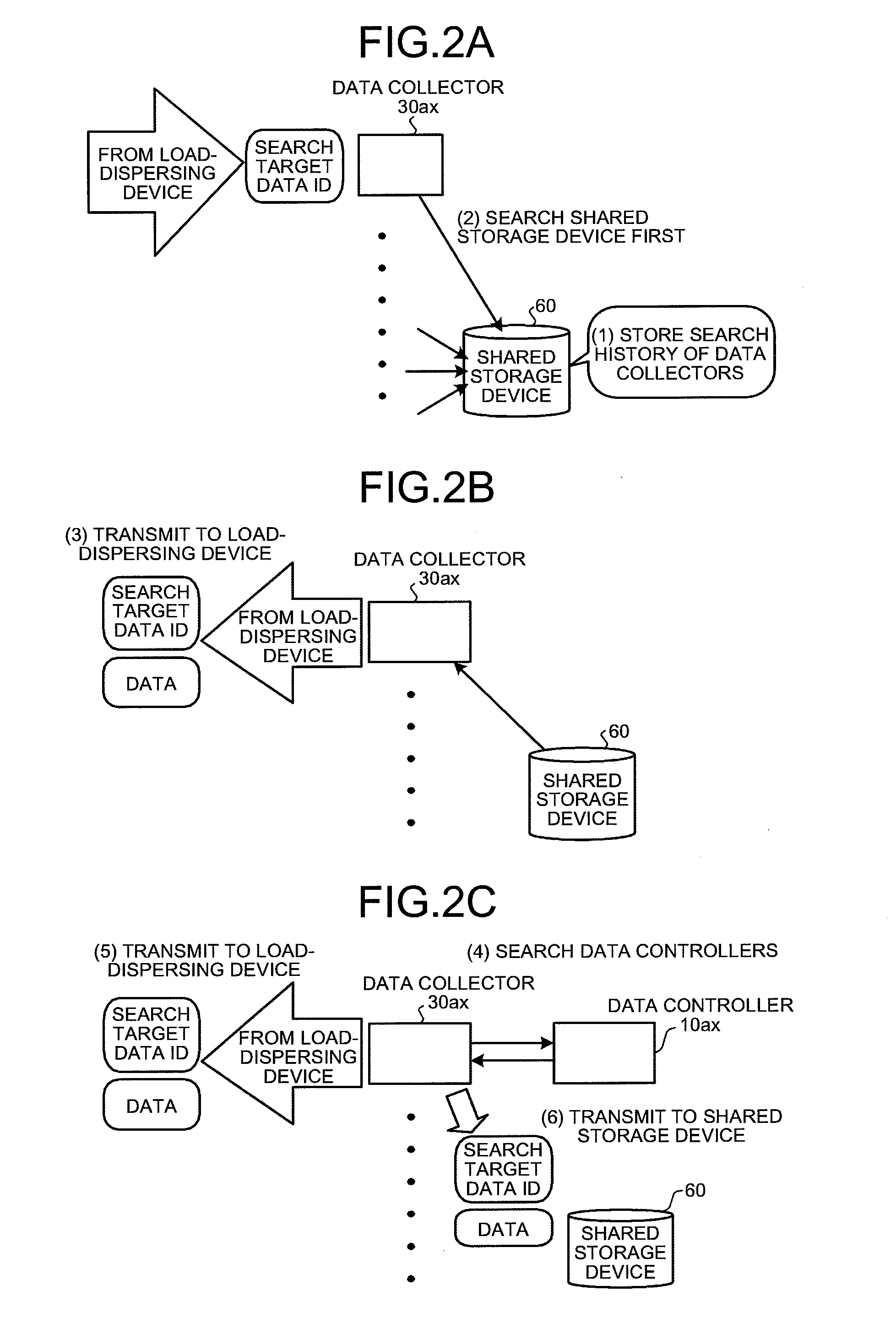
[0060]A structure of the data collector 30ax, which is included in the network control system shown in FIGS. 1 to 2C, is explained next with reference to FIG. 6. FIG. 6 is a block diagram of the data collector 30ax.
[0061]As shown in FIG. 6, the data collector 30ax includes an input-output control interface 70, a storage unit 80, and a controller 90. The input-output control interface 70 controls a data transfer between the controller 90 and the load-dispersing device 40, the shared storage device 60, and the data controllers 10a1 to 10an.
[0062]The storage unit 80 stores therein data and computer programs that are necessary for various processes by the controller 90. Especially, the storage unit 80 includes a reference table storage unit 81 that is closely related to the present invention.
[0063]The reference table storage unit 81 stores therein identification data of the data controllers that enables to uniquely identify the data controllers 10a1 to 10an. To be specific, as shown ...
second embodiment
[0086]The structure of the data collector 30ax is explained next with reference to FIG. 10. FIG. 10 is a block diagram of the data collector 30ax.
[0087]As shown in FIG. 10, similarly as the first embodiment, the data collector 30ax includes the input-output control interface 70, the storage unit 80, and the controller 90. Further, the storage unit 80 includes a reference table storage unit 82 and the controller 90 includes the search target data ID analyzer 91, the first searching unit 92, a second searching unit 94, and a periodic searching unit 95. Components, which carry out the same operations as the respective operations in the first embodiment, are referred using the same reference numerals and an explanation is omitted. Thus, only the reference table storage unit 82, the second searching unit 94, and the periodic searching unit 95 are explained below.
[0088]The reference table storage unit 82 stores therein the search target data ID that is used as the representative search ...
third embodiment
[0099]The structure of the data collector 30ax is explained next with reference to FIG. 14. FIG. 14 is a block diagram of the data collector 30ax.
[0100]As shown in FIG. 14, similarly as the second embodiment, the data collector 30ax includes the input-output control interface 70, the storage unit 80, and the controller 90. Further, the storage unit 80 includes a reference table storage unit 83 and the controller 90 includes the search target data ID analyzer 91, the first searching unit 92, the second searching unit 94, the periodic searching unit 95, and a deletion controller 96. Components, which carry out the same operations as the respective operations in the second embodiment, are referred using the same reference numerals and an explanation is omitted. Thus, only the reference table storage unit 83 and the deletion controller 96 are explained below.
[0101]The reference table storage unit 83 stores therein data for enabling the periodic searching unit 95 to determine a necessi...
PUM
 Abstract
Description
Claims
Application Information
 - R&D
- Intellectual Property
- Life Sciences
- Materials
- Tech Scout
- Unparalleled Data Quality
- Higher Quality Content
- 60% Fewer Hallucinations
Browse by: Latest US Patents, China's latest patents, Technical Efficacy Thesaurus, Application Domain, Technology Topic, Popular Technical Reports.
© 2025 PatSnap. All rights reserved.Legal|Privacy policy|Modern Slavery Act Transparency Statement|Sitemap|About US| Contact US: help@patsnap.com


