Cooling System for Body Armour

a body armour and cooling system technology, applied in the field of personal armour, can solve the problems of inconvenience for wearers, inability to efficiently utilize the power of perspiration to cool the body, and damage to the physiological make up of the body

Inactive Publication Date: 2008-06-19
KAPAH YOAV +3
View PDF7 Cites 30 Cited by
  • Summary
  • Abstract
  • Description
  • Claims
  • Application Information

AI Technical Summary

Problems solved by technology

Personal armour typically blocks the flow of air around the body such that in hot conditions perspiration cannot be utilized efficiently to cool the body.
The excessive build-up of heat at the body surface causes inconvenience to the wearer of the armour and in extreme cases of build up of heat, the physiological make up of the body can be damaged.

Method used


Image

  • Cooling System for Body Armour
  • Cooling System for Body Armour
  • Cooling System for Body Armour

Examples


Embodiment Construction

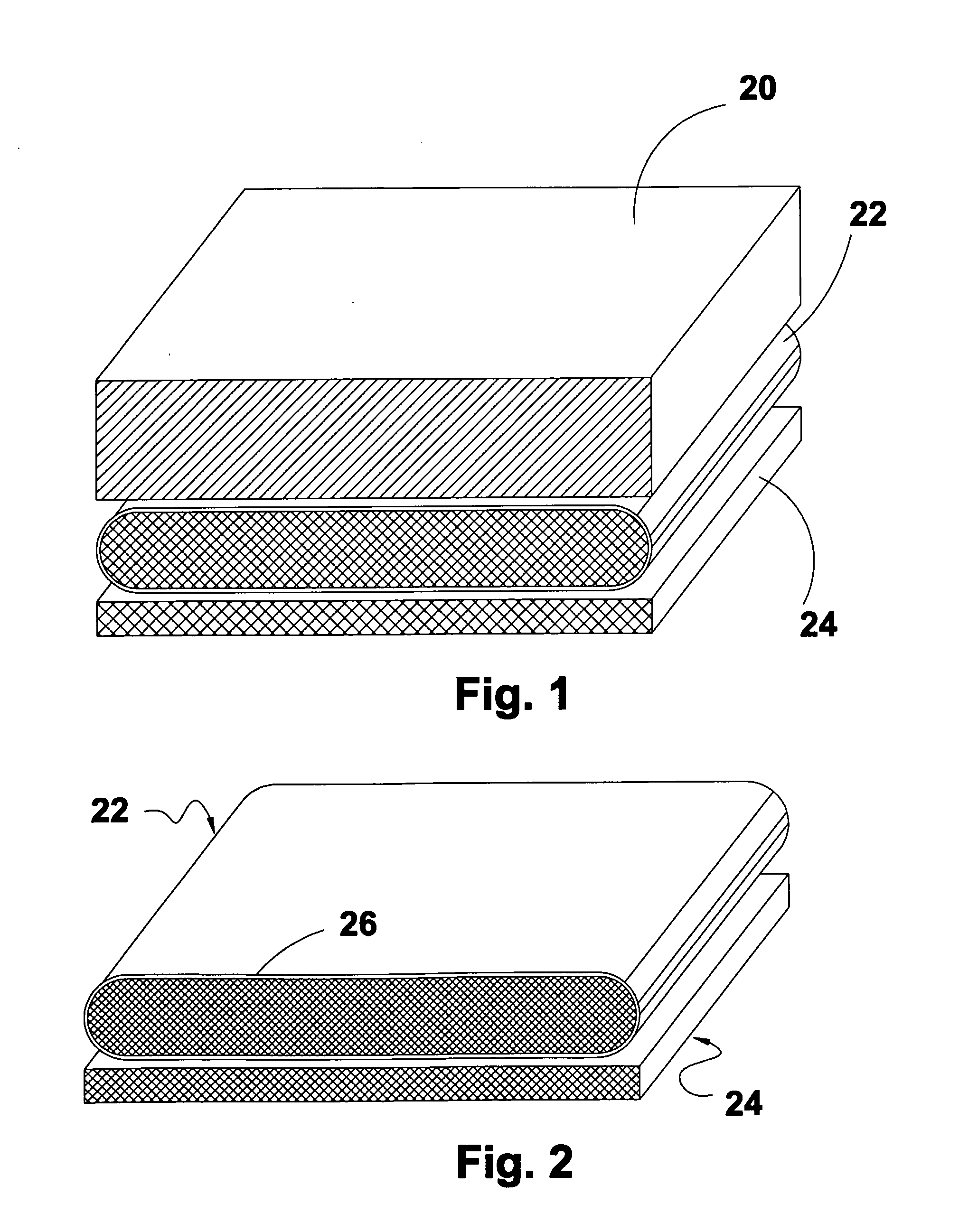
[0007]In accordance with the present invention, a set of voluminous layers is disposed between the wearer of personal armour and his / her garments or body. The set is described schematically with reference to FIG. 1. Layer 20 represents the armour layer which is drawn for the sake of simplicity as a unitary layer but in reality may possess a compound structure. Layer 22 is the outermost layer of the set of the invention and layer 24 is the body contact layer, which juxtaposes the wearer's own garments or exposed body. Of the set of voluminous layers, layer 22 is enveloped by an impervious shell as is described schematically with reference to FIG. 2 to which reference is now made. In a cross sectional view, layer 22 juxtaposes body contact layer 24. Shell 26 envelopes layer 22, however not as shown, the shell completely wraps the layer. In more particular reference to the issue of relationships between the personal dress of the wearer and the body armour, there is no significance as t...


PUM


Abstract

A system for providing streaming air to evaporate perspiration from a wearer of personal armour. The system incorporates a set of voluminous layers for wearing beneath the armour, one of which is enveloped voluminous layer. The envelope is perforated in the direction of said wearer, such that an air blower forces air into the perforation and thence onto the body of the wearer.

Description

TECHNICAL FIELD OF THE INVENTION[0001]The present invention is in the field of personal armour worn by individuals as protection against projectiles, bullets and the like. More specifically the present invention deals with measures for cooling the body of the wearer covered by such protective armour.BACKGROUND OF THE INVENTION[0002]Excessive heat produced by the human body is dissipated by perspiration. The evaporation of the perspiration takes up heat from the body, thus producing a cooling effect. Personal armour typically blocks the flow of air around the body such that in hot conditions perspiration cannot be utilized efficiently to cool the body. The wearing of personal armour promotes the build-up of excessive heat at and around the surface area of the wearer. This observation is evident but stressed if the wearer is engaged in physical activity such as walking, running or working. Under hot environmental conditions the build-up of heat may be quick and permanent. The excessiv...

Claims


Application Information

Patent Timeline
Patent Type & Authority Applications(United States)
IPC IPC(8): F41H1/02A41D13/002B08B15/00F41H
CPCF41H1/02A41D13/0025
Inventor KAPAH, YOAVRAVIV, ALONBAR-EREZ, EYALSPECTOR, YUVAL
Owner KAPAH YOAV
Why Eureka
Try Eureka