Cooling Suit

a technology of cooling suit and body, applied in the field of cooling suit, can solve the problems of continuously and uselessly exuding perspiration, inability to obtain the required amount of heat radiation, and inability to protect the human body, etc., and achieve the effect of expanding an effective area

Inactive Publication Date: 2007-03-08
SEFT DEVMENT LAB
View PDF2 Cites 43 Cited by
  • Summary
  • Abstract
  • Description
  • Claims
  • Application Information

AI Technical Summary

Benefits of technology

[0010] The cooling suit according to the present invention is capable of causing a large amount of air to flow between an undergarment or wearer's body and a guide sheet so as to largely extend an effective area under the influence of a physiological cooling ability of the wearer to thereby cool the wearer's body.
[0011]FIG. 1A is a schematic front view of a cooling suit according to a first embodiment of the present invention when it is worn, and FIG. 1B is a schematic rear view of the cooling suit.
[0012]FIG. 2 is a schematic side view of the vicinity of a parallel airstream generation device attached to a garment 2.
[0013]FIG. 3A is a schematic front view of a fan casing of the parallel airstream generation device, and FIG. 3B is a partially sectioned schematic side view thereof.
[0014]FIG. 4A is a schematic front view of a sideward-flow fan of the parallel airstream generation device, and FIG. 4B is a schematic cross-sectional view thereof viewed in a direction of arrow A-A′.
[0015]FIG. 5A and FIG. 5B are schematic cross-sectional views showing relationships among the garment 2, a fan 3, and an undergarment 13, respectively.

Problems solved by technology

It is possible to regard a human as an extremely inefficient working device which ingests food to conduct life support activities, pieces of work, and the like, and to generate heat commensurately therewith.
Due to the inefficiency, most of caloric intake is turned into heat, thereby requiring radiation of a large amount of heat commensurating with a then quantity of work in order to keep a normal body temperature.
However, it becomes impossible to obtain a required quantity of heat radiation when vaporization of perspiration is disabled depending on conditions of temperature, humidity, presence / absence of airstreams, quantity of work, and the like, such that perspiration is continuously and uselessly exuded in a liquid state without vaporization, thereby causing not only uncomfortableness but also physiological damages.

Method used


Image

  • Cooling Suit
  • Cooling Suit
  • Cooling Suit

Examples


first embodiment

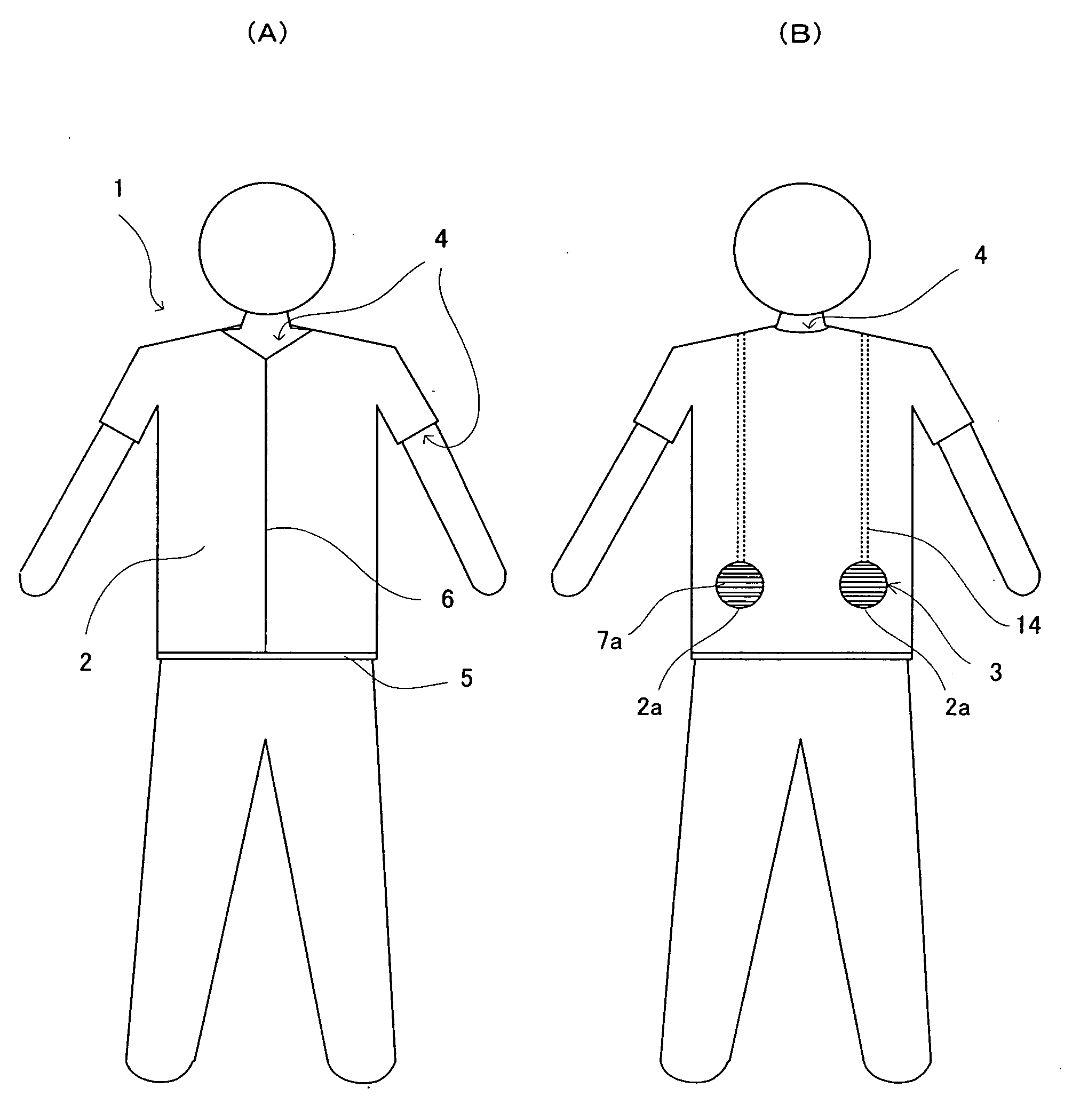
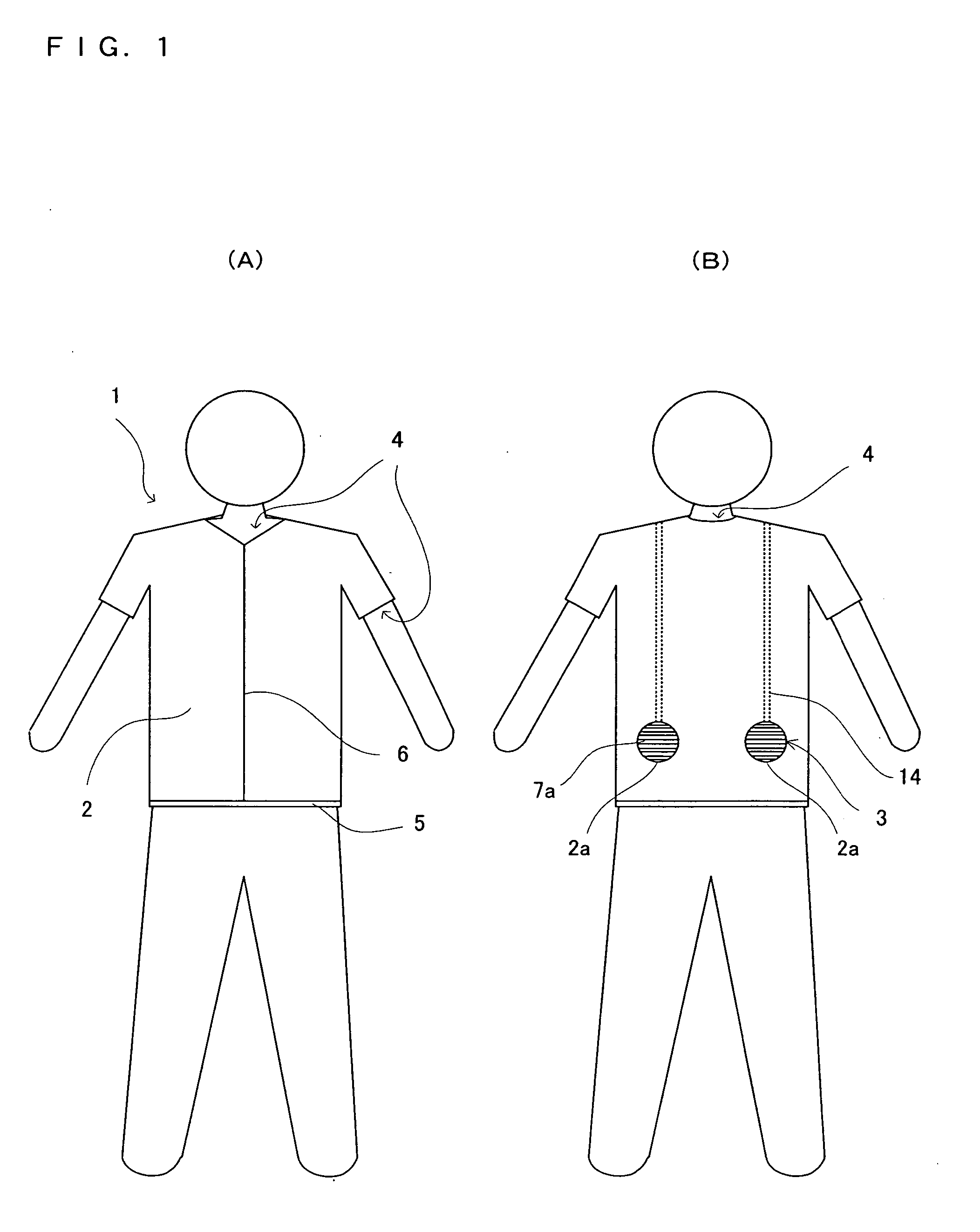
[0063] There will be explained a best mode for carrying out the present invention according to the present application. There is provided a cooling suit according to a first embodiment of the present invention applied to a short-sleeved jacket of a worksuit. FIG. 1A is a schematic front view of the cooling suit according to the first embodiment of the present invention when it is worn, and FIG. 1B is a schematic rear view of the cooling suit. As shown in FIG. 1, the cooling suit 1 of the first embodiment comprises: a garment or jacket 2 formed into a shape of a short-sleeved jacket and simultaneously serving as a guide sheet (the meaning of “guide” will be described later) which is less in air leakage; parallel airstream generation devices 3 provided at the lower right and left of a back side of the garment, respectively, to introduce outside air to thereby generate airflows between the garment 2 and an undergarment or wearer's body and parallelly to the wearer's body; air exit port...

second embodiment

[0084] There will be explained a second embodiment of the present invention with reference to the drawings. The second embodiment is applied to a worksuit having a cooling capacity higher than that of the cooling suit of the first embodiment. The second embodiment has an air blowing capacity of about 20 m3 / H which is two times that of the first embodiment. The second embodiment is differentiated from the first embodiment, because, in the second embodiment: there is adopted a propeller as vanes of each parallel airstream generation device, instead of a vane wheel; there is provided a new air exit portion provided with an air permeation sheet, as an exit of air; and there is provided a fixation belt as fixation means for preventing a large fan from being swung due to a movement of a wearer's body. Other configuration is the same as that in of the first embodiment. Thus, like reference numerals as used in the first embodiment are used to denote elements of the second embodiment having ...

third embodiment

[0092] There will be explained a third embodiment of the present invention. The third embodiment is different from the first embodiment and second embodiment, in that the former includes a fixation belt having not only fans but also an electric-power source (battery), cords and the like, attached thereto. Other points are the same as those in the second embodiment. Thus, like reference numerals as used in the second embodiment are used to denote elements of the third embodiment having the same functions as the second embodiment, and the detailed description thereof will be omitted. FIG. 10A is a schematic view of this embodiment in a state where the fixation belt 160 of this embodiment is developed. The fixation belt 160 of this embodiment has a width larger than a diameter of each fan 3, and has two fans 3, electric power supply cords 32, and an electric-power source 33 detachably attached to the belt. Thus, the fixation belt 160 can be regarded as an item realized by eliminating a...


PUM


Abstract

The present invention aims at providing a cooling suit having a simple structure and capable of assuredly vaporizing a large amount of perspiration. To this end, there is provided a cooling suit to be worn on a wearer, comprising: an air inlet 2a configured to introduce outside air; parallel airstream generation means 3 for introducing the outside air through the air inlet to generate parallel airstreams which are substantially parallel to the wearer's body; a guide sheet simultaneously serving as a garment 2 and for guiding the parallel airstreams generated by the parallel airstream generation means, parallelly to the wearer's body; an air exit portion configured to discharge the parallel airstreams to the exterior; and electric-power source means for supplying electric power to the parallel airstream generation means; wherein the parallel airstream generation means cooperatively blows air of a total amount of about 5 m3/H to 500 m3/H into between the guide sheet and an undergarment or wearer's body to cause positive pressures between the guide sheet and the undergarment or wearer's body to thereby produce an air flow space therebetween, and the parallel airstream generation means causes the blown air to flow through the air flow space to thereby discharge moisture due to perspiration to the exterior and to thereby constantly feed fresh outside air into the air flow space, thereby largely intensifying conditions where perspiration can be evaporated.

Description

TECHNICAL FIELD [0001] The present invention relates to a cooling suit configured to cool a wearer's body by causing outside air to flow along the wearer's body parallelly thereto. BACKGROUND ART [0002] It is possible to regard a human as an extremely inefficient working device which ingests food to conduct life support activities, pieces of work, and the like, and to generate heat commensurately therewith. Due to the inefficiency, most of caloric intake is turned into heat, thereby requiring radiation of a large amount of heat commensurating with a then quantity of work in order to keep a normal body temperature. To this end, humans each possesses a physiological ability for cooling his / her body by virtue of perspiration. Namely, there is determined a physiologically required quantity of heat radiation commensurately with a quantity of work, and perspiration is exuded commensurately therewith, in a manner to attain heat radiation which is most suitable for the then situation of him...

Claims


Application Information

Patent Timeline
Patent Type & Authority Applications(United States)
IPC IPC(8): A41D13/00A41D13/002A41D13/02A41D27/28
CPCA41D13/0025A41D31/14A41D13/0056A41D27/28
Inventor ICHIGAYA, HIROSHI
Owner SEFT DEVMENT LAB
Why Eureka
Try Eureka