Medical Monitoring System

a monitoring system and medical technology, applied in the field of medical alarm systems, can solve the problems of not providing a method of determining

Inactive Publication Date: 2015-10-29
GEOB INT
View PDF12 Cites 42 Cited by
  • Summary
  • Abstract
  • Description
  • Claims
  • Application Information

AI Technical Summary

Benefits of technology

[0011]The following presents a simplified summary of the invention in order to provide a basic understanding of some aspects of the invention. This summary is not intended as an extensive overview of the invention. It is not intended to identify key / critical elements of the invention. Its sole purpose is to present some concepts of the invention in a simplified form as a prelude to the more detailed description that is presented later.

Problems solved by technology

U.S. Pat. No. 7,052,472 B1 however does not provide for relaying of a medical emergency alert to a remote care-giver or a remote monitoring station.
U.S. Pat. No. 7,052,472 B1 further does not disclose transmission of a medical alert to a remote care-giver or a remote monitoring station by either wire-line or wireless communication channels.
US2009 / 0322513 A1 however fails to disclose a alerting system that, provisions for production of an audible alarm to a wearer of the wearable monitoring device in the event the wearable monitoring device is not tightly coupled to the wearer utilizing the measurement obtained by the physiological condition sensor to consequently alert the subject that the wearable monitoring device is improperly worn.
U.S. Pat. No. 7,978,063 similar to US 2009 / 0322513 A1 does not provide a method of determining whether the wearable monitoring device i.e. wearable monitor is firmly attached to the surface of the skin of a subject being monitored utilizing the measurement obtained by the physiological condition sensor to consequently alert the subject that the wearable monitoring device is improperly worn.
Moreover similar to U.S. Pat. No. 7,978,063 B2 does not disclose a system that augments a wireless communication channel for the communication of an alert with either a combination of a wireless communication channel, wire-line communication channel or fibre optic communication channel.
In addition US 2011 / 0160547 A1, does not disclose a wireless transmission device that generates an alert based on measured physiological parameters that fall beyond a predetermine threshold of measurement values, with the threshold values being customizable according to age, gender and medical condition of a particular individual.

Method used


Image

  • Medical Monitoring System
  • Medical Monitoring System
  • Medical Monitoring System

Examples


Embodiment Construction

[0058]The detailed description set forth below in connection with the appended drawings is intended as a description of exemplary embodiments and is not intended to represent the only form in which the embodiments may be constructed and / or utilized. The description sets forth the functions and the sequence for constructing the exemplary embodiments. However, it is to be understood that the same or equivalent functions and sequences may be accomplished by different embodiments that are also intended to be encompassed within the scope of this disclosure.

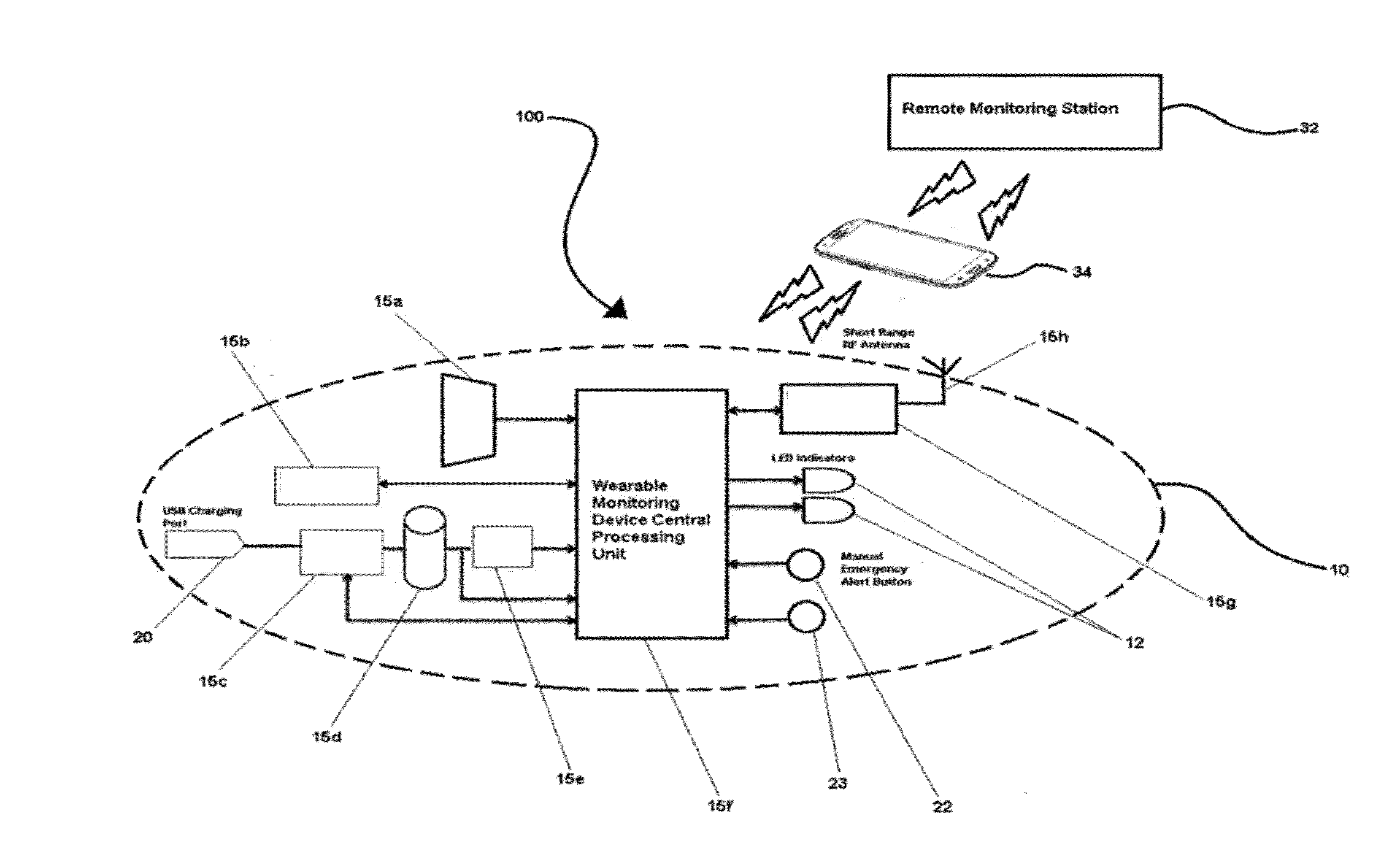
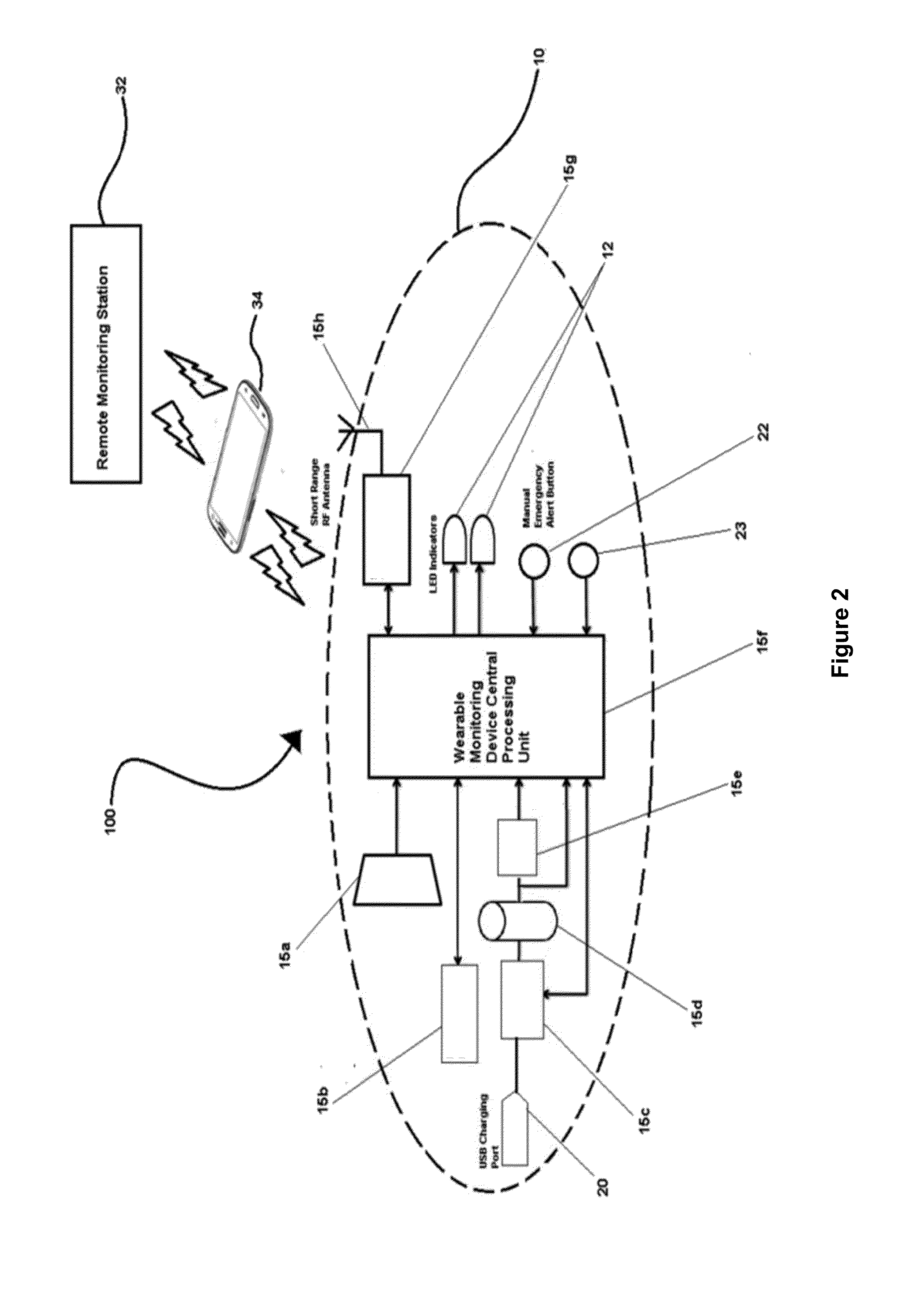
[0059]The medical monitoring system (100) of the present invention will now be described with reference to FIGS. 2 to 10.

[0060]With reference to FIGS. 2 and 3, in a preferable embodiment, the present invention provides a medical monitoring system (100) for remote monitoring of an individual's physiological parameters that comprises of a wearable monitoring device (10) and a wireless transceiver unit (34).

[0061]In another preferable emb...


PUM


Abstract

The present invention relates to a medical monitoring system (100) that comprises at least one wearable monitoring device (10) and a wireless transceiver unit (34). The medical monitoring system (100) serving to provision for the monitoring of at least one mobile subject's physiological parameters that include body temperature or perspiration, analyze physiological parameter measurements embodied in the form of electrical signals, produce a medical alert signal in the event the physiological parameter measurements fall beyond predetermined threshold values and further serve to wirelessly transmit the medical alert signal and electrically embodied physiological parameter measurements to a remote monitoring station (32).

Description

[0001]The present invention relates broadly to the field of medical monitoring and emergency alert systems. More particularly the present invention relates to a medical monitoring and emergency alert system that provides for wireless transmission of a medical alert to a remote monitoring station to consequently enable remote monitoring and personal emergency response despatch.BACKGROUND TO THE INVENTION[0002]A medical alarm system is an alarm system designed to signal presence of a medical hazard requiring urgent attention and to summon a medical emergency personnel. Other terms for medical alarm systems include but are not limited to “Personal Emergency Response System” and “Wireless Medical Emergency Alert Systems”.[0003]A medical monitoring system on the other hand is designed to continuously or periodically transmit electrically embodied physiological parameter measurements embodied as RF signals to a remote monitoring station for physiological monitoring of a subject as well as...

Claims


Application Information

Patent Timeline
Patent Type & Authority Applications(United States)
IPC IPC(8): A61B5/00A61B5/0205A61B5/053A61B5/01
CPCA61B5/746A61B5/01A61B5/4266A61B5/02055A61B5/0537A61B5/0008A61B2560/0475A61B5/6843A61B5/742A61B5/747A61B5/681A61B2560/0214A61B5/0017G08B21/0446G08B21/0453G08B25/005G08B25/009G08B25/016
Inventor TAN, GEOFFREY WENG LENGBEH, BRANDON
Owner GEOB INT
Why Eureka
Try Eureka