Eureka AIR delivers breakthrough ideas for toughest innovation challenges, trusted by R&D personnel around the world.

Mounting head and associated methods

Active Publication Date: 2008-06-19
INTUITIVE CORP
View PDF18 Cites 2 Cited by
  • Summary
  • Abstract
  • Description
  • Claims
  • Application Information

AI Technical Summary

Problems solved by technology

When a point of interest is found with a conventional tripod head, it may be easily lost if the optical device is bumped or moved when in an unlocked position.
The point of interest, whether a landmark or an animal, may be difficult to relocate once lost from the field of view of the optical device.
However, just the act of locking the tripod head in a desired position can cause the tripod head to shift out of the desired position.
Additionally, locks require time and effort that can cause a viewer to miss a photo opportunity or miss spotting an animal or other object of interest.
Other optical devices may be imbalanced, causing creep from the position to which the optical device is set.

Method used


Image

  • Mounting head and associated methods
  • Mounting head and associated methods
  • Mounting head and associated methods

Examples


Embodiment Construction

[0031]It will be understood that the components of the present invention, as generally described and illustrated in the Figures herein, may be arranged and designed in a wide variety of different configurations. Thus, the following more detailed description of the embodiments of the apparatus and method of the present invention, as represented in FIGS. 1 through 20, is not intended to limit the scope of the invention, which is as broad as claimed herein. The illustrations merely depict embodiments of the invention. These embodiments of the invention will be best understood by reference to the drawings, wherein like parts are designated by like numerals. Those of ordinary skill in the art will, of course, appreciate that various modifications to the details of the figures may easily be made without departing from the scope of the invention.

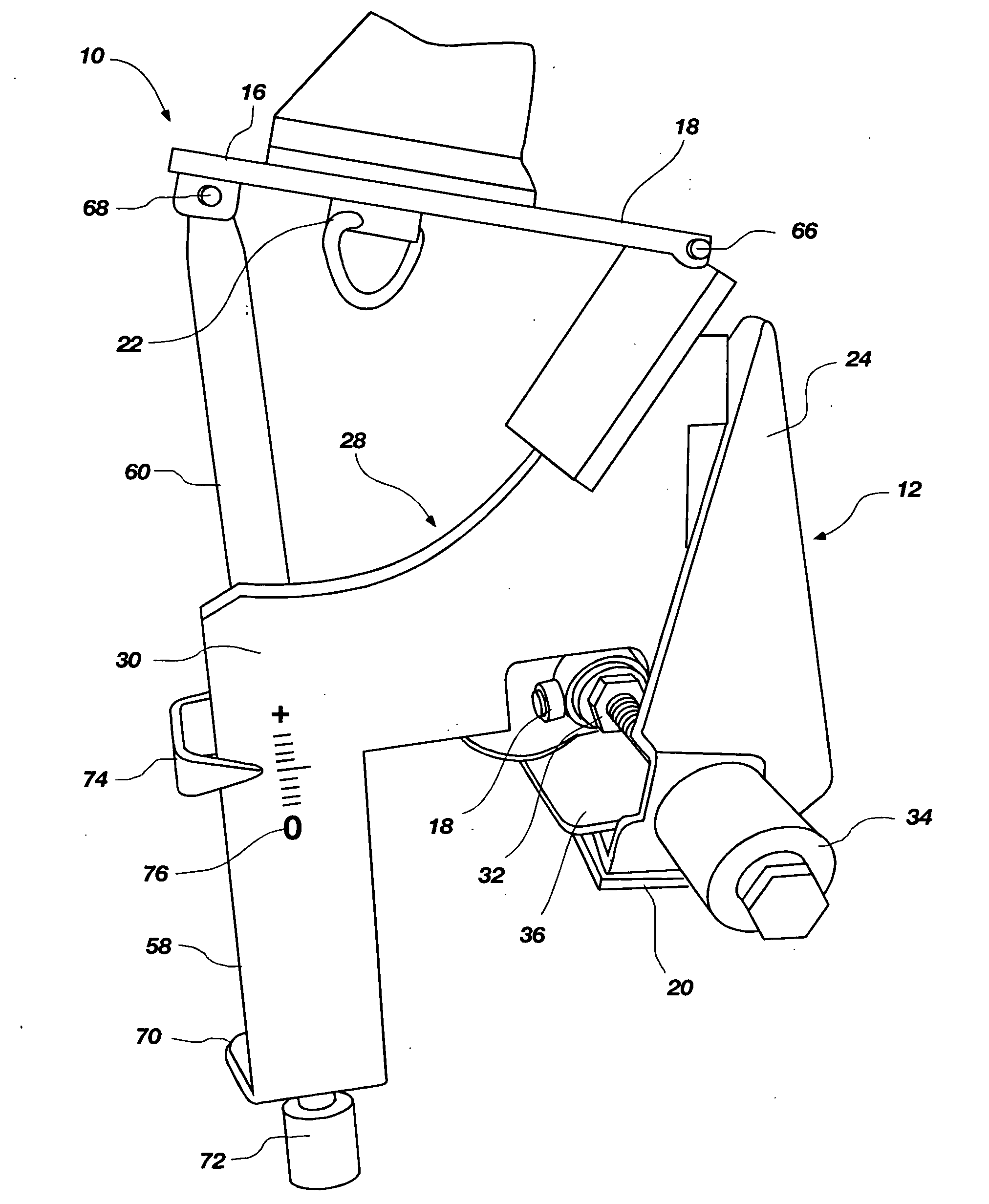
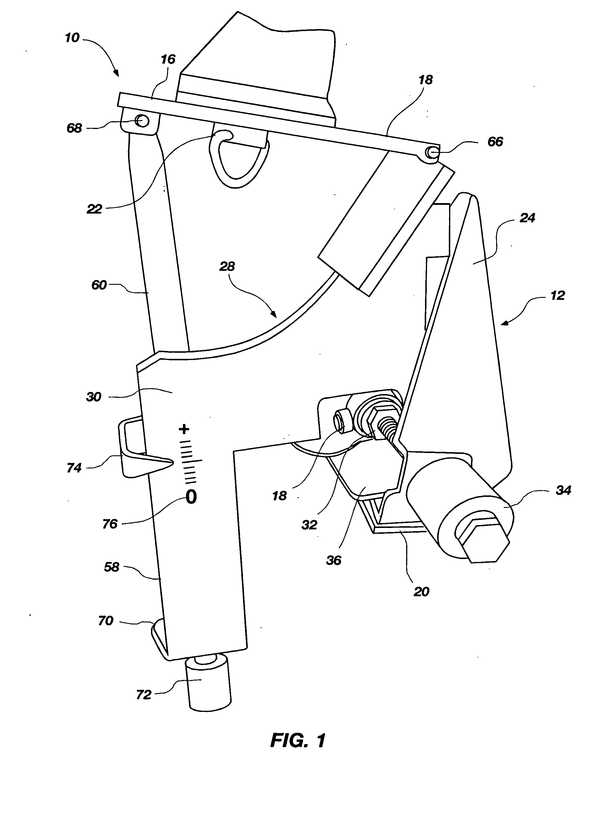
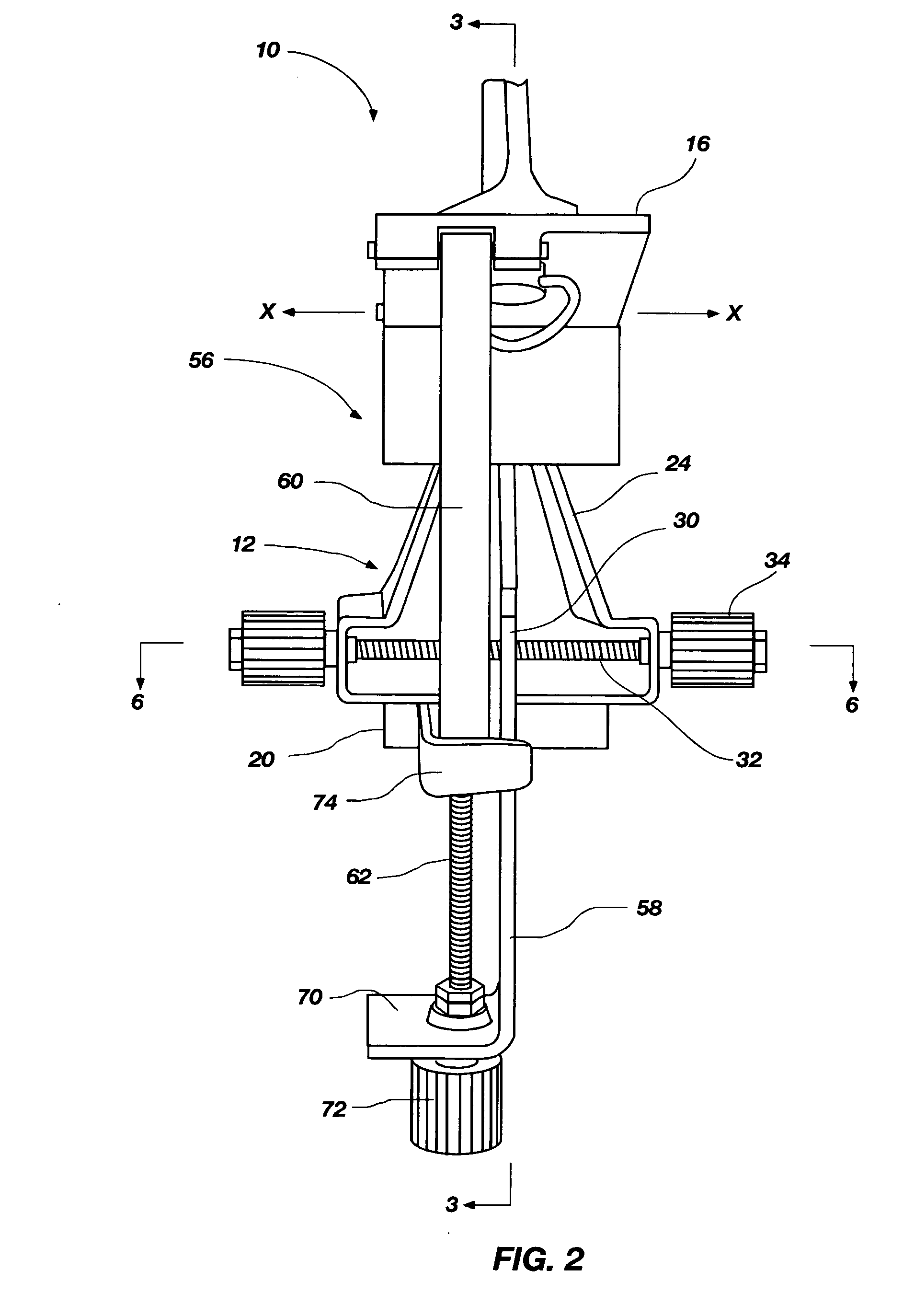
[0032]Referring to FIGS. 1 and 2, a first embodiment of tripod head 10 of the present invention is shown. The tripod head 10 may include a base 12...


PUM


Abstract

A mounting head includes a first pivot assembly and a second pivot assembly. The first pivot assembly may be configured to pivot a platform of the mounting head about a first axis, and the second pivot assembly may be configured to pivot the platform about a second axis. A pivot assembly may comprise a threaded shaft having an attachment element configured to move linearly along the axial length of the threaded shaft as the threaded shaft is rotated. The linear movement of the attachment element may drive pivotal movement of the platform. The mounting head may further include position indicators, configured for indicating, in linear coordinates, the position of the platform. Methods of using and adjusting a mounting head are disclosed.

Description

FIELD OF THE INVENTION[0001]The present invention, in various embodiments, relates generally to camera and similar optical device mounts. More specifically, embodiments of the present invention relate to heads for adjustably mounting a device on a tripod or other support structure.BACKGROUND OF THE INVENTION[0002]Cameras and other optical devices such as scopes, binoculars, laser transits, and camcorders are often mounted on a tripod or other support by a head that enables panning by rotating about a vertical axis and tilting by rotating about a horizontal axis. Panning and tilting enable a user to search an area for a target or locate a point of interest with an optical device. Typical examples are using a telescope to locate astronomical phenomenon, using a spotting scope or binoculars to locate an animal while hunting or bird watching etc., or using a camera to find and photograph a point of interest.[0003]Conventional tripod heads usually include a base that mounts on the tripod...

Claims


Application Information

Patent Timeline
IPC IPC(8): F16M11/12
CPCF16M11/10F16M11/2014F16M11/18F16M11/12
Inventor CLAMPITT, DARWIN
Owner INTUITIVE CORP
Why Eureka
Eureka Blog
Learn More