
Ocular implants for placement in schlemm's canal

a technology of ocular implants and schlemm's canal, which is applied in the field of ocular implants, can solve the problems of affecting the function of the ocular implant, the damage to adjacent tissue, and the relative high fluid flow rate of the device at or around the device, so as to facilitate the flow of aqueous humor and facilitate the flow

Active Publication Date: 2010-06-22
ALCON INC
View PDF175 Cites 83 Cited by
  • Summary
  • Abstract
  • Description
  • Claims
  • Application Information

AI Technical Summary

Benefits of technology

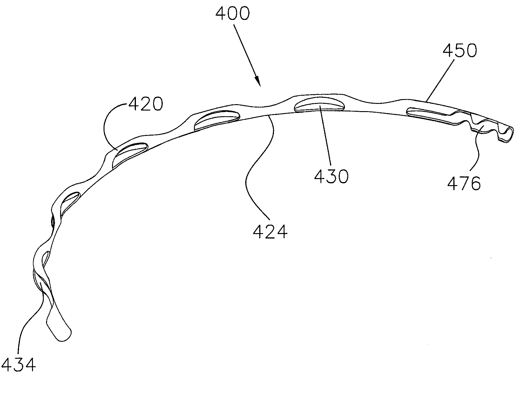
[0011]Some exemplary ocular implants disclosed in this document comprise a body having a plurality of open areas, strut areas and spine areas formed therein. The strut areas and spine areas act as reinforcing structures that hold the walls of Schlemm's canal in an patent state so that the walls of the canal provide a flow channel or fistula. Furthermore, the spine areas and the strut areas may be sized and shaped to reinforce Schlemm's canal while occupying a relatively small portion of the total lateral cross sectional area of Schlemm's canal. When this is the case, the ocular implant provides minimal obstruction to aqueous humor flowing along the length of Schlemm's canal. Reinforcing Schlemm's canal with minimal metal mass present in the canal may also encourage a safe healing response over time.
[0024]In some patients, Schlemm's canal may have become compartmentalized. When this is the case, Schlemm's canal becomes a series of small compartments separated by discontinuities or partitions. As the ocular implant is advanced into Schlemm's canal, the distal tip of the ocular implant penetrates the discontinuities / partitions. This penetrating action re-establishes fluid communication between adjacent compartments. The body of the ocular implant facilitates flow across the partitions by remaining in Schlemm's canal after fluid communication has been re-established.
[0025]Some exemplary ocular implants disclosed herein include a blunt tip having a generally rounded shape. For example, the blunt tip may have a generally hemispherical shape. The generally rounded shape of the blunt tip may increase the likelihood that the body of the ocular implant will track Schlemm's canal as the ocular implant is advanced into the canal during an implant procedure.
[0026]Some exemplary ocular implants disclosed in this document include an inlet portion that is shaped and sized to extend through the trabecular meshwork of the eye. This inlet portion may provide a flow path between the anterior chamber and Schlemm's canal. After entering Schlemm's canal, aqueous humor may flow between a proximal portion of the ocular implant and an intermediate portion of the ocular implant. The intermediate portion of the ocular implant may be conceptualized as a manifold that distributes the aqueous humor along a portion of Schlemm's canal. A plurality of outlets may be located along the length of this portion of Schlemm's canal. When this is the case, the presence of the ocular implant in Schlemm's canal facilitates the flow of aqueous humor through those outlets.

Problems solved by technology

While some prior glaucoma treatment implants did provide a flow path between the anterior chamber and Schlemm's canal, these prior devices failed to recognize (1) the importance of supporting a significant portion of Schlemm's canal in a patent state or (2) the harm to adjacent tissue caused by relatively high fluid flow rates at or around any portion of the device.

Method used


Image

  • Ocular implants for placement in schlemm's canal
  • Ocular implants for placement in schlemm's canal
  • Ocular implants for placement in schlemm's canal

Examples


Embodiment Construction

[0046]The following detailed description should be read with reference to the drawings, in which like elements in different drawings are numbered identically. The drawings, which are not necessarily to scale, depict exemplary embodiments and are not intended to limit the scope of the invention. Examples of constructions, materials, dimensions, and manufacturing processes are provided for selected elements. All other elements employ that which is known to those of skill in the field of the invention. Those skilled in the art will recognize that many of the examples provided have suitable alternatives that can be utilized.

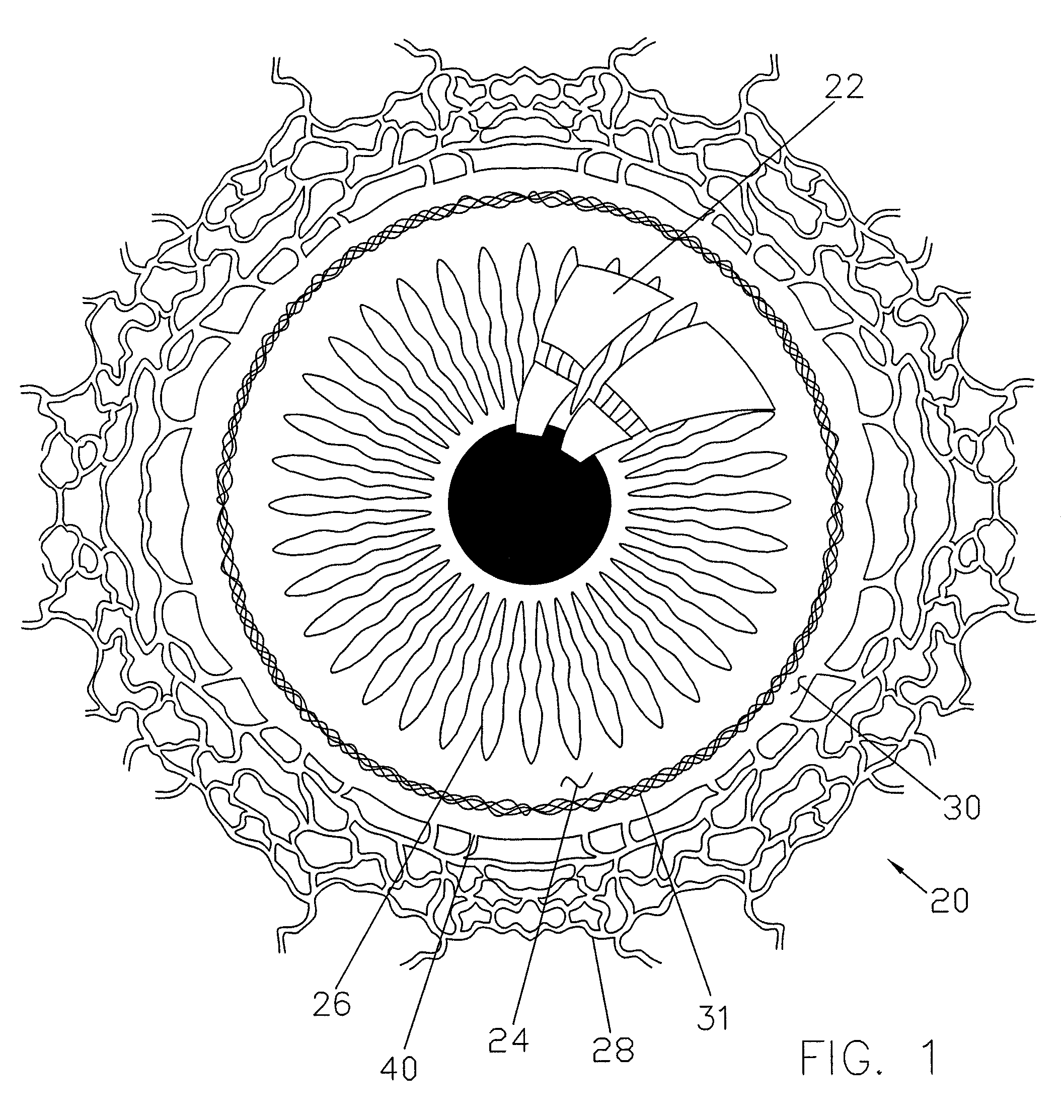
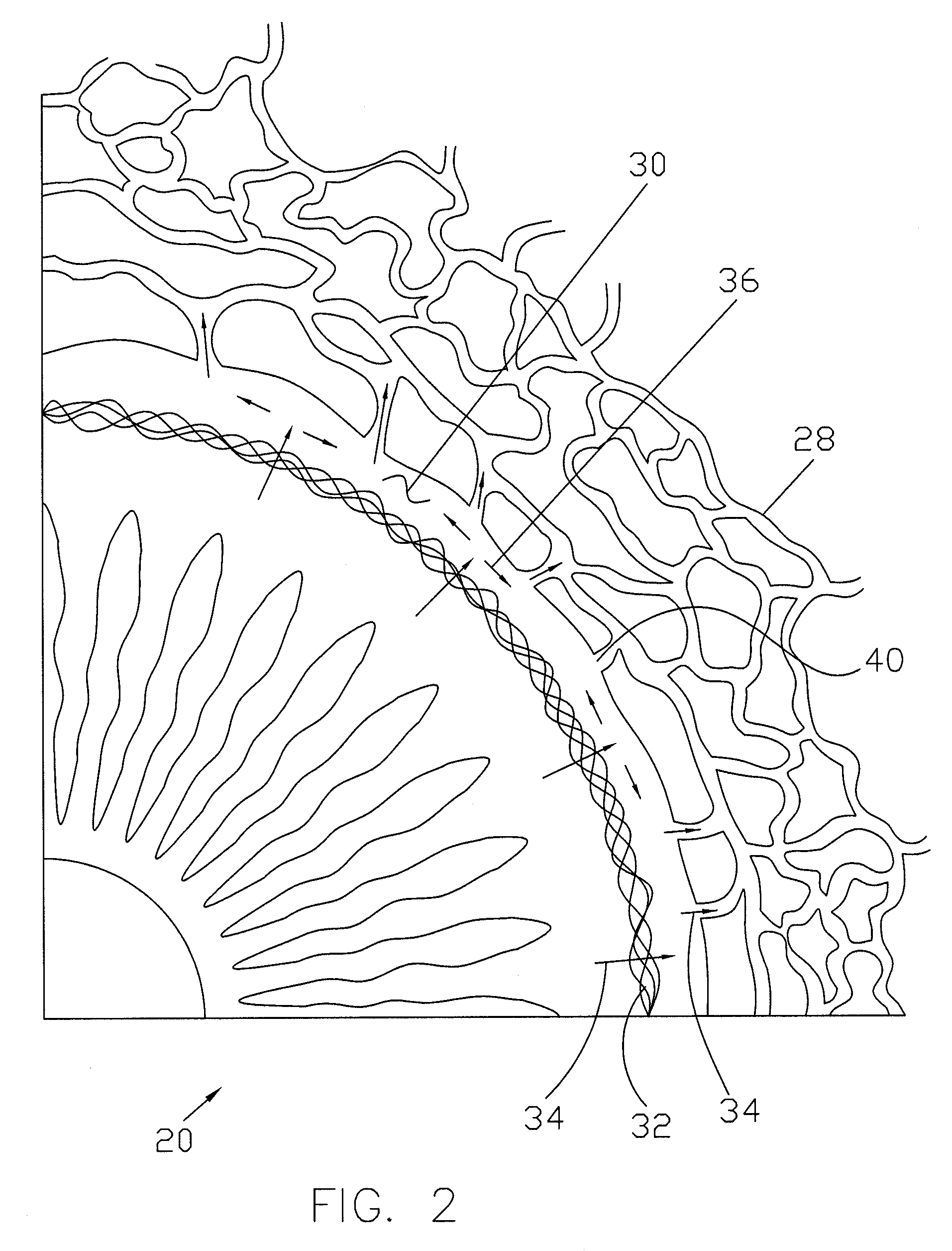
[0047]FIG. 1 is a plan view showing a portion of an eye 20. A reflection on the outer surface of the cornea 22 of eye 20 is visible in FIG. 1. Cornea 22 encloses an anterior chamber 24 of eye 20. The iris 26 of eye 20 is visible through cornea 22 and anterior chamber 24. Anterior chamber 24 is filled with aqueous humor which helps maintain the generally hemispherical...


PUM


Abstract

An ocular implant adapted to reside at least partially in a portion of Schlemm's canal of an eye. In some embodiments the implant has a body extending in a curved volume whose longitudinal axis forms an arc of a circle, and a plurality of open areas and strut areas formed in the body, the open areas extending over more than 50% of a surface defining the curved volume, the strut areas surrounding the open areas, the body having a diameter of between 0.005 inches and 0.04 inches. The invention also provides a method of treating glaucoma including the steps of supporting tissue forming Schlemm's canal in an eye with an implant extending at least partially in the canal along an axial length within the canal; and contacting with the implant less than 50% of the tissue forming the canal along the axial length.

Description

FIELD OF THE INVENTION[0001]The present invention relates generally to devices that are implanted within the eye. More particularly, the present invention relates to devices that facilitate the transfer of fluid from within one area of the eye to another area of the eye.BACKGROUND OF THE INVENTION[0002]According to a draft report by The National Eye Institute (NEI) at The United States National Institutes of Health (NIH), glaucoma is now the leading cause of irreversible blindness worldwide and the second leading cause of blindness, behind cataract, in the world. Thus, the NEI draft report concludes, “it is critical that significant emphasis and resources continue to be devoted to determining the pathophysiology and management of this disease.” Glaucoma researchers have found a strong correlation between high intraocular pressure and glaucoma. For this reason, eye care professionals routinely screen patients for glaucoma by measuring intraocular pressure using a device known as a to...

Claims


Application Information

Patent Timeline
Patent Type & Authority Patents(United States)
IPC IPC(8): A61M27/00
CPCA61F9/00781A61M27/002A61F9/0017A61M2210/0612A61F2009/00891
Inventor SCHIEBER, ANDREW T.EUTENEUER, CHARLES L.
Owner ALCON INC
Learn More