Ultrasound probe positioning immersion shell

a technology of ultrasound probes and immersion shells, applied in medical science, eye inspection, diagnostics, etc., can solve the problems of corneal compression, corneal abrasion, post-operative optical error, etc., and achieve the effect of improving operator visualization

Active Publication Date: 2005-05-12
ESI
View PDF7 Cites 82 Cited by
  • Summary
  • Abstract
  • Description
  • Claims
  • Application Information

AI Technical Summary

Benefits of technology

[0022] The general purpose of the present invention is to provide an ultrasound probe positioning immersion shell. To achieve the objectives for correct ultrasound probe positioning during immersion A-scan, an ultrasound probe positioning immersion shell, a unique immersion shell, has been developed. The ultrasound probe positioning immersion shell consistently places the ultrasound probe perpendicular to and at the correct distance from the corneal plane. The ultrasound probe positioning immersion shell has a fluid flow arrangement to ensure suitable filling of a lower chamber while minimizing 
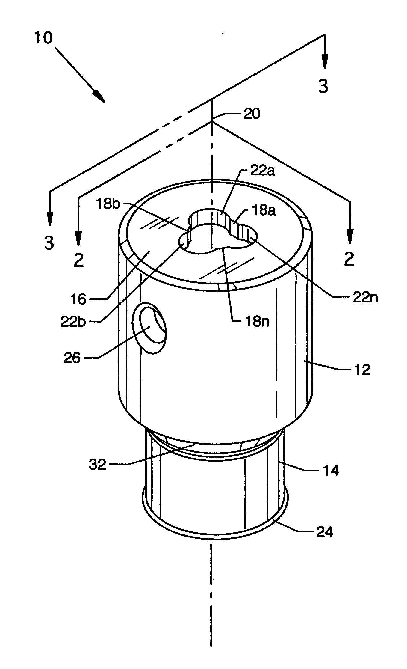
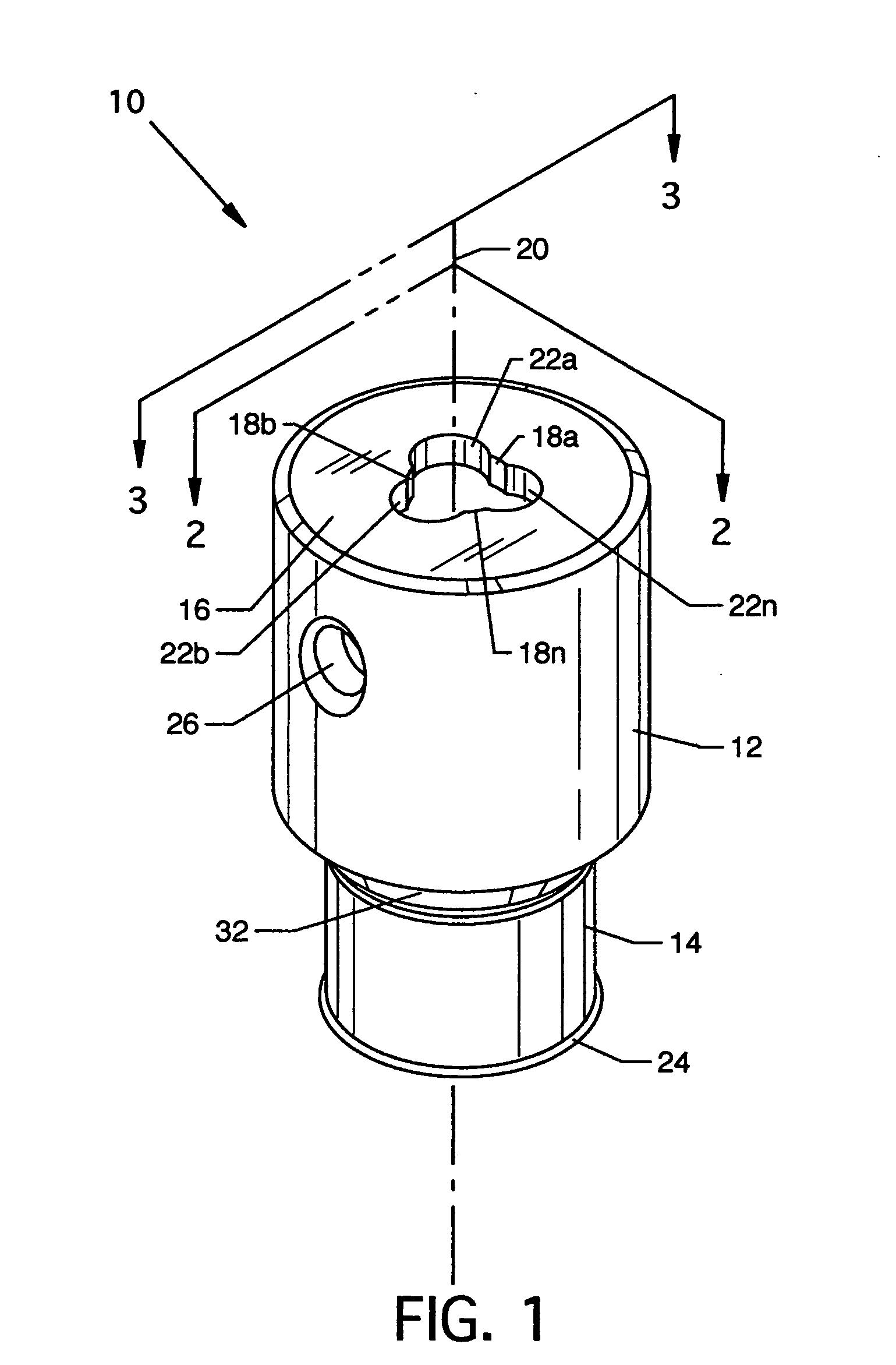
air bubble formation which can disrupt or otherwise influence the ultrasound measuring process. The preferred methods to achieve the perpendicular ultrasound probe position are to have one continuous guide or, preferably, to have two or more separate opposed guide rings which can be externally and internally located with each having centrally located structures providing at least three arcuate guide surfaces for intimate contact with the cylindrical or tapered shape of an ultrasound probe, respectively. The configuration of each of the externally and internally located guide rings includes centrally located arcuate guide surfaces which accommodate the ultrasound probe and, additionally, at least include three vents which can be arcuate, which are offset from the centerline of the ultrasound probe positioning immersion shell, and which intersect the centrally located arcuate guide surfaces, thereby creating a 
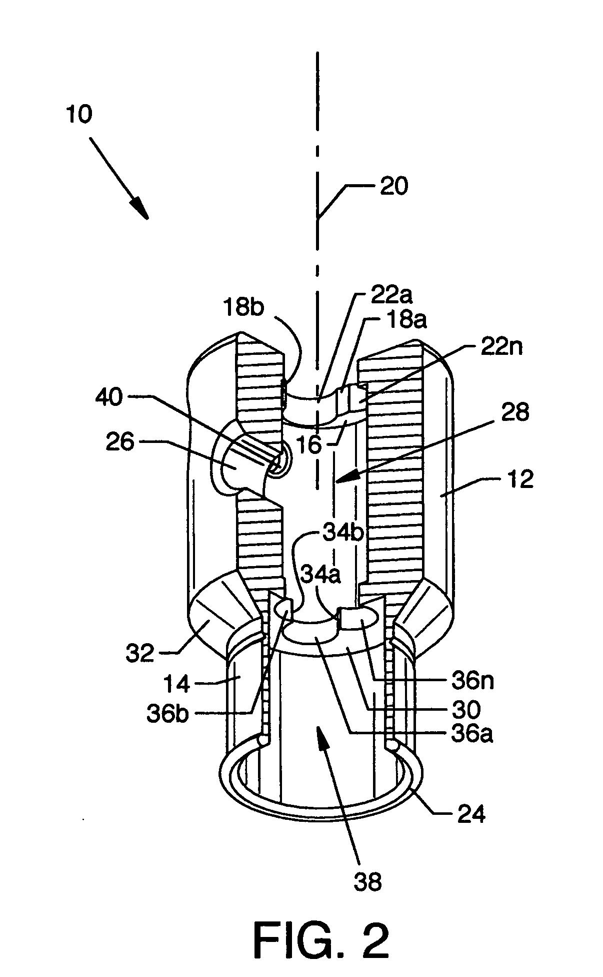
scallop-like pattern. This pattern creates at least three points of ultrasound probe contact at each guide ring location and at least three vents about the intersection of the ultrasound probe and the respective external and internal guide rings. Two or more guide rings, used for positioning the ultrasound probe, result in partial defining of separate internal upper and lower chambers, where the upper chamber is between the external guide ring, the internal guide ring and an upper cylindrical body, and where the lower chamber, which is open at one end, is bounded by the internal guide ring and a lower cylindrical body and a lip. The vents in the internal guide ring allow for the transfer of liquid medium to drain from the upper chamber to the lower chamber. The external guide ring pattern allows for air pressure equalization to ambient air when liquid medium is introduced and when the ultrasound probe is centered in the external guide ring. Self-positioning of the ultrasound probe transducer is accomplished by the arcuate guide surfaces of the external and internal guide rings contacting the ultrasound probe at a minimum of two separate body regions to ensure perpendicular positioning of the ultrasound probe in the ultrasound probe positioning immersion shell. A fluid transfer port located in the upper portion of the ultrasound probe positioning immersion shell allows for various methods of filling the liquid medium. The fluid transfer port is located away from the base of the ultrasound probe positioning immersion shell so that it will be away from the eye to improve operator visualization during placement of the instrument. The ultrasound probe positioning immersion shell can be fashioned of transparent material to monitor placement on the eye and to monitor the liquid medium level.

Problems solved by technology

An inaccurate axial length measurement of just one millimeter can result in a post-operative optical error of three diopters, enough to necessitate a second surgery.
The biometrist must ensure that neither ointment nor excess fluid (e.g., anesthetic drops or tears) are present on the cornea prior to beginning the examination, since even a small amount of fluid may lead to erroneous axial length readings.
Disadvantages of the contact technique include both corneal compression and the possibility of corneal abrasion.
Further, due to examiner parallax or alignment problems, it is often difficult to be sure measurements are taken from the center of the cornea.
An inaccurate axial length measurement of only 1 mm can result in a significant post-operative refractive error.
The presence of air bubbles can disrupt the sound wave transmission and interfere with axial length measurement.
Because the ultrasound probe is free to move, it can be easily moved vertically and tilted, resulting in erroneous measurements.
Further, a viscous solution, Goniosol, is required, which is expensive and leaves a vision-blurring film.
Achieving accurate measurements using this shell design is difficult to master.
This can result in vertical and angled error due to a single fulcrum contact point, as with mating two cones with different dimensions and angles.
This reduces the ability to visually place the shell and ultrasound probe on the eye due to the port and any connected tubing blocking the view.
Furthermore, due to the ultrasound probe blocking the air from escaping from the lower chamber, a large air bubble can be easily trapped in the lower chamber and prevent an ultrasound axial length measurement.
If the ultrasound probe tip is either too low or too high, a faulty reading will occur.
Any sharp object in close proximity to the eye is considered a safety issue.

Method used


Image

  • Ultrasound probe positioning immersion shell
  • Ultrasound probe positioning immersion shell
  • Ultrasound probe positioning immersion shell

Examples


Embodiment Construction

[0056]FIG. 1 is an isometric view of the ultrasound probe positioning immersion shell 10, and FIG. 2 is a re-oriented cutaway view in partial cross section along line 2-2 of FIG. 1 showing additional internally located elements of the ultrasound probe positioning immersion shell 10. Outwardly and readily visible elements of the ultrasound probe positioning immersion shell 10 include an upper cylindrical body 12 tapering to a lower cylindrical body 14, an external guide ring 16 extending across the upper region of the upper cylindrical body 12, a plurality of guide surfaces 18a-18n, preferably being arcuate, extending through the external guide ring 16 and having a common radius centered along the central axis 20 of the ultrasound probe positioning immersion shell 10, a plurality of external vents 22a-22n, preferably being arcuate, extending through the external guide ring 16 and having like radii offset from the central axis 20 of the ultrasound probe positioning immersion shell 10 ...


PUM


Abstract

An ophthalmologic appliance being an ultrasound prob positioning immersion shell for use in ultrasonic measurement of axial length of the eye ophthalmology and other procedures. Support members in an upper chamber and a lower chamber each provides accommodating support along and about a central axis of the ultrasound probe positioning immersion shell and about vertically spaced regions of ultrasound probes to provide for perpendicular alignment of ultrasound probes to the corneal plane. Vents in the chamber structure allow for introduction of fluid medium and for the expelling of air from the chambers to inhibit bubble formation.

Description

CROSS REFERENCES TO RELATED APPLICATIONS [0001] None. BACKGROUND OF THE INVENTION [0002] 1. Field of the Invention [0003] The present invention is an ultrasound probe positioning immersion shell that positions and aligns a diagnostic or therapeutic device, such as an ultrasound transducer probe, for the purpose of immersion of the eye for ultrasound axial length measurement, anterior chamber depth measurement, retinal detail measurement, or other diagnostic or therapeutic applications requiring alignment with the long axis of the eye. [0004] 2. Description of the Prior Art [0005] There are several situations in the treatment of an ophthalmic patient that require a diagnostic ultrasound examination providing detailed information of the anatomical structures of the eye. This information enables the physician to provide the best possible care for a large variety of ocular disorders. [0006] The most frequent use of ultrasound in ophthalmology is the axial eye length A-scan used to measu...

Claims


Application Information

Patent Timeline
Patent Type & Authority Applications(United States)
IPC IPC(8): A61B3/10A61B8/00A61B8/10
CPCA61B8/10A61B8/4281A61B8/4209
Inventor BURBA, THOMAS A.HARDTEN, DAVID R.PRAGER, THOMAS C.
Owner ESI
Why Eureka
Try Eureka