Bone cement mixing and delivery device with releasable mixing blade

a technology of bone cement and mixing blade, which is applied in the direction of osteosynthesis devices, prosthesis, teeth capping, etc., can solve the problems of not ensuring the complete delivery of bone cement into the patient, fragments that could contaminate the bone cement, and high undesirable exposure, so as to reduce the introduction of contaminants into the mixture, minimize the handling, and reduce the effect of cos

Inactive Publication Date: 2006-11-14
STRYKER CORP
View PDF39 Cites 39 Cited by
  • Summary
  • Abstract
  • Description
  • Claims
  • Application Information

AI Technical Summary

Benefits of technology

[0016]The subject invention provides many advantages over conventional systems. First, the bone cement is mixed and dispensed from the same container, thus eliminating the need to manually transfer the bone cement from a mixing vessel to a dispensing device. In addition, the removable handle is released rather than broken off. Thus, cost is reduced, handling is minimized and the introduction of contaminants into the mixture is minimized or eliminated. Furthermore, the compound is not exposed to air, thereby reducing or eliminating exposure of noxious and toxic vapors to surrounding personnel during the surgical operation. Another advantage of the subject invention is that the compound is mixed in an environment evacuated by a vacuum. Thus, the formation of air bubbles is minimized, providing a uniform reaction product and, in turn, producing a stronger bone cement compound.

Problems solved by technology

Due to the noxious and toxic nature of such vapors, it is highly undesirable to be exposed to them, particularly for extended periods of time in the course of multiple preparations.
The dispensing system, however, is separate and exposes the mixed cement to the surrounding personnel.
Conventional systems incorporate frangible handles that when broken may produce fragments that could contaminate the bone cement.
A portion of the bone cement remains in the discharge nozzle and thus the system does not ensure complete delivery of the bone cement into the patient.
One disadvantage of this system is that the bone cement must have a relatively low viscosity to be pulled by the auger into the delivery chamber.
Additionally, the bone cement may remain on the walls of the mixing chamber where the paddle is unable to reach it.

Method used


Image

  • Bone cement mixing and delivery device with releasable mixing blade
  • Bone cement mixing and delivery device with releasable mixing blade
  • Bone cement mixing and delivery device with releasable mixing blade

Examples


Embodiment Construction

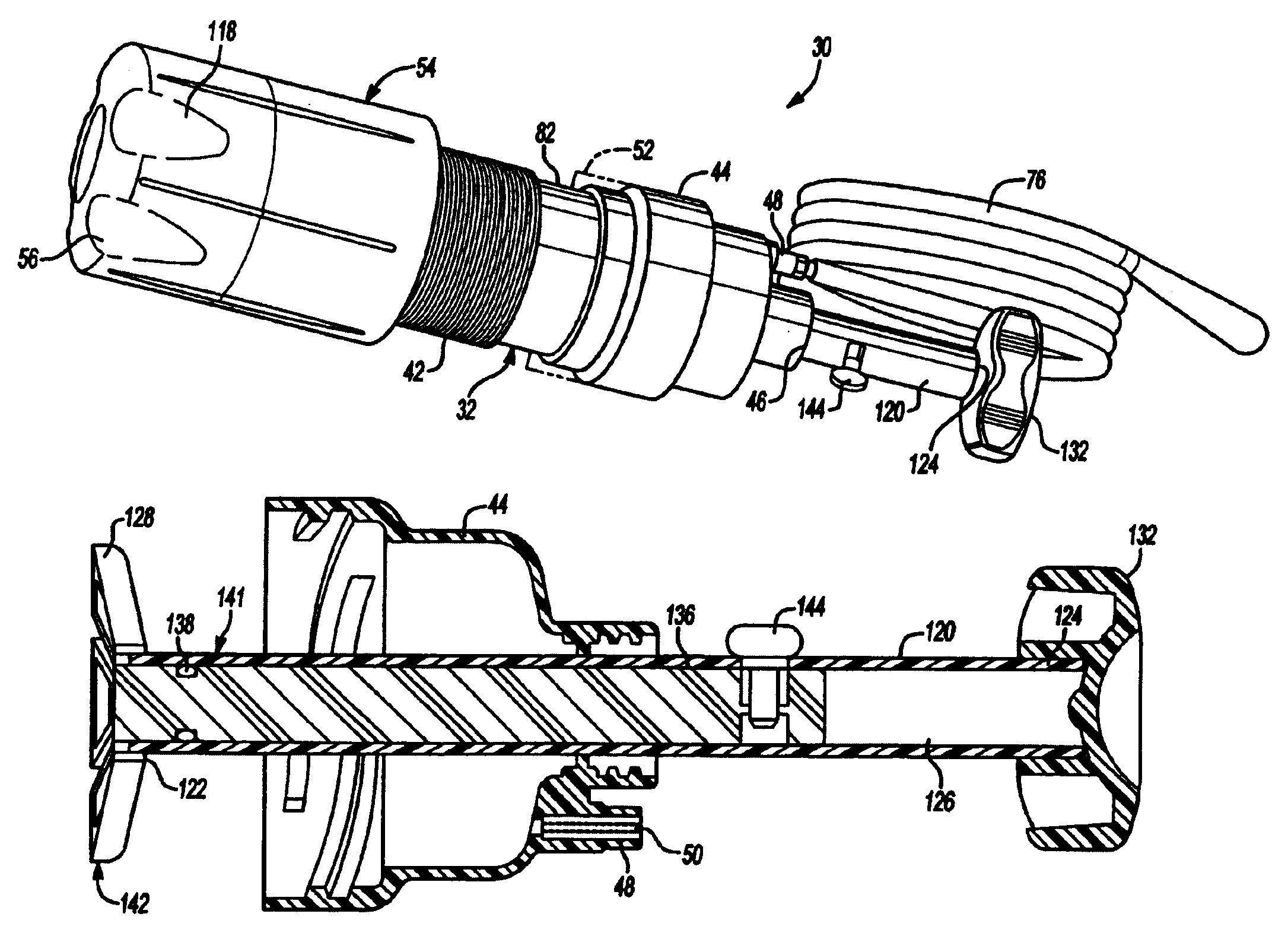
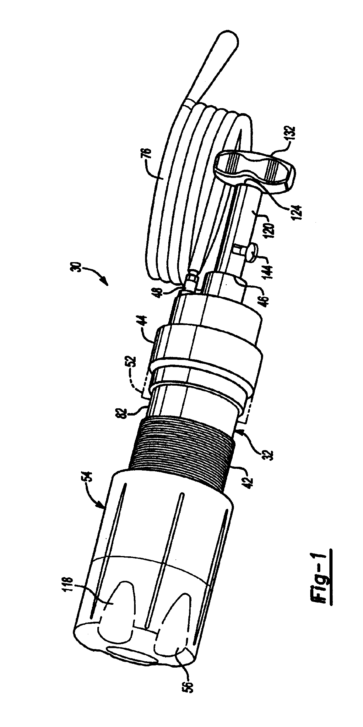
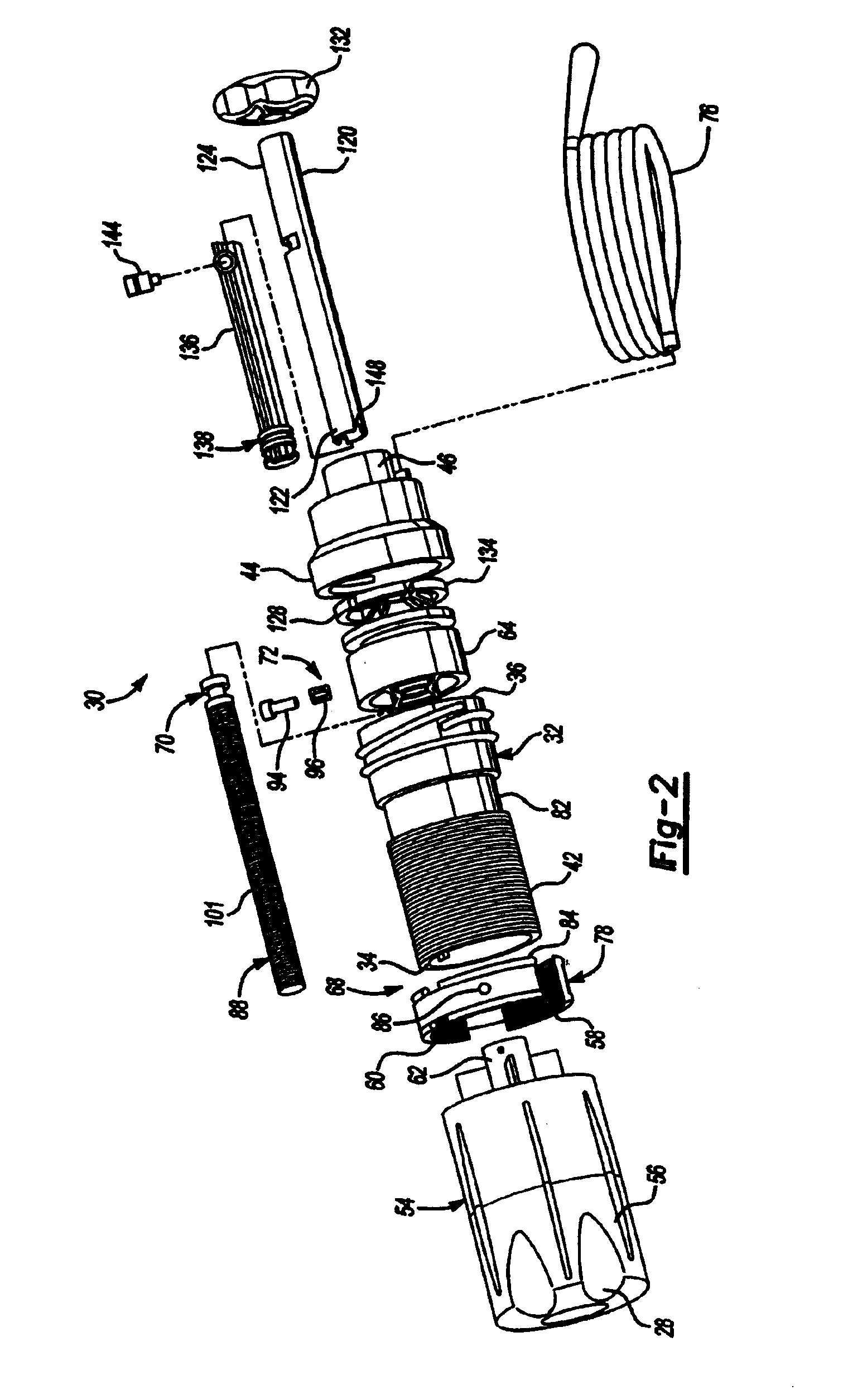
[0044]Referring to the Figures, wherein like numerals indicate like or corresponding parts throughout the several views, a bone cement mixing and delivery assembly for mixing a powdered copolymer and a liquid monomer to form a bone cement and delivering the bone cement is shown generally at 30. In one embodiment, delivery of the bone cement is performed percutaneously. Percutaneous, as used in the medical field, relates to passing or effectuating the bone cement through the skin. The mixing and delivery assembly 30 functions in three phases comprising a mixing phase, a transfer phase, and a delivery phase. All phases are described in detail below with the transfer and delivery phases described first, followed by the mixing phase. Specifically, FIGS. 5–7 and FIGS. 17–21 show the assembly 30 during the transfer and delivery phases. FIGS. 1–4 illustrate the assembly 30 during the mixing phase.

[0045]The mixing and delivery assembly 30 includes a cartridge 32 (shown separately in FIG. 13...


PUM

PropertyMeasurementUnit
strengthaaaaaaaaaa
rigidityaaaaaaaaaa
areaaaaaaaaaaa

Abstract

A bone cement mixing and delivery assembly is disclosed for mixing a powdered copolymer and a liquid monomer to form a bone cement and delivering the bone cement. The assembly includes a cartridge having a distal end and a proximal end and defining a mixing chamber between the distal end and the proximal end. A transfer mechanism having a cap and a stem supporting a piston and a plunger is connected to the distal end. The transfer mechanism includes a first advancement mechanism for advancing the piston and plunger in unison and a second advancement mechanism for moving the plunger independent of the piston. The assembly further includes a removable handle having a shaft for attachment of a mixing blade and a quick-release connector and a release button for locking and unlocking the mixing blade from the removable handle.

Description

[0001]This application is a divisional of U.S. patent application Ser. No. 10 / 229,349 filed Aug. 27, 2002, now U.S. Pat. No. 6,736,537, which is a continuation of U.S. patent application Ser. No. 09 / 981,552 filed Oct. 17, 2001, now U.S. Pat. No. 6,547,432, which claims priority to U.S. Provisional Patent Application Ser. No. 60 / 325,783 filed Jul. 16, 2001.FIELD OF THE INVENTION[0002]The present invention relates generally to a bone cement delivery assembly, one that is particularly suited for mixing a powdered copolymer and a liquid monomer to form a bone cement and delivering the bone cement.BACKGROUND OF THE INVENTION[0003]In many surgical procedures, particularly orthopedic procedures, it is common practice to affix a prosthesis to a bone or joint structure for improving the strength, rigidity and movement of the bone / joint structure. Such prosthetic devices have been widely used, hip joints and knee joints are the most common examples of areas where prosthetic devices are used t...

Claims


Application Information

Patent Timeline
Patent Type & Authority Patents(United States)
IPC IPC(8): B01F7/00A61C5/04A61C13/00A61F2/28A61F2/46A61L27/00B01F11/00B01F13/00B01F15/02B01J4/02
CPCA61B17/8822B01F11/0082B01F13/002A61B17/8827A61B2017/8838B01F31/441B01F33/5011
Inventor COFFEEN, JARED P.HUYSER, RICHARD F.TAGUE, CHRISTOPHER M.PERNSTEINER, WESTONSTRATTON, DENNIS A.
Owner STRYKER CORP
Why Eureka
Try Eureka