Method for manufacturing an optical fibre laser

a technology feedback loops, which is applied in the direction of manufacturing tools, instruments, optical elements, etc., to achieve the effect of discharging the heat produced in optical fibres and ensuring the stability of optical fibre lasers

Active Publication Date: 2016-02-23
COMMISSARIAT A LENERGIE ATOMIQUE ET AUX ENERGIES ALTERNATIVES
View PDF19 Cites 0 Cited by
  • Summary
  • Abstract
  • Description
  • Claims
  • Application Information

AI Technical Summary

Benefits of technology

[0012]By means of the method according to the invention, it is checked that the optical fibre output remains correctly polarised throughout a pump power range, and not for only one value. In this way, when the optical fibre laser is used with a nominal pump power within the previous range, the output polarisation of the laser remains stable even in the event of fluctuations in the pump power relative to the nominal value thereof.
[0021]Optionally, filling the trough with heat-conducting material may be carried out drop by drop so as to minimise air bubble formation.
[0026]On the contrary, in an optical fibre laser according to the invention, the heat-conducting material is suitable for dissipating the heat produced in the optical fibre, rendering the behaviour of the optical fibre laser more stable.

Problems solved by technology

Indeed, the inventors discovered that this instability problem was due to the method for manufacturing the optical fibre laser.
However, the inventors ascertained that the slightest modification of the pump power could give rise to a shift in the operating point, and thus the instability described above.

Method used


Image

  • Method for manufacturing an optical fibre laser
  • Method for manufacturing an optical fibre laser
  • Method for manufacturing an optical fibre laser

Examples


Embodiment Construction

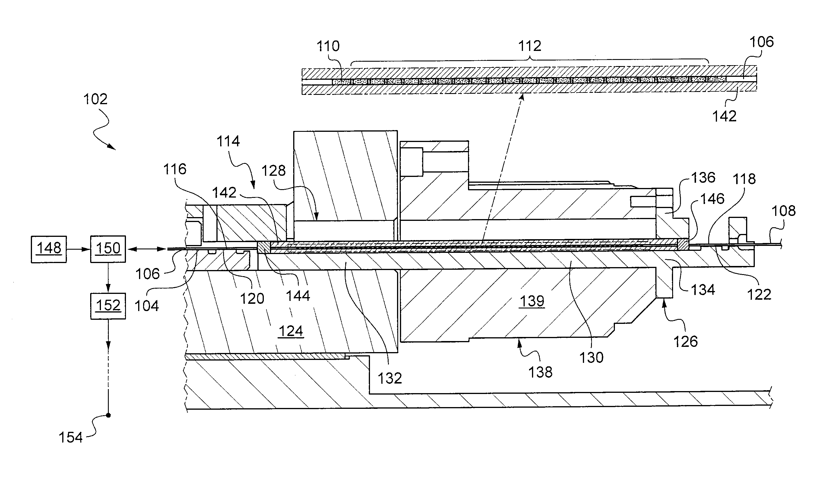
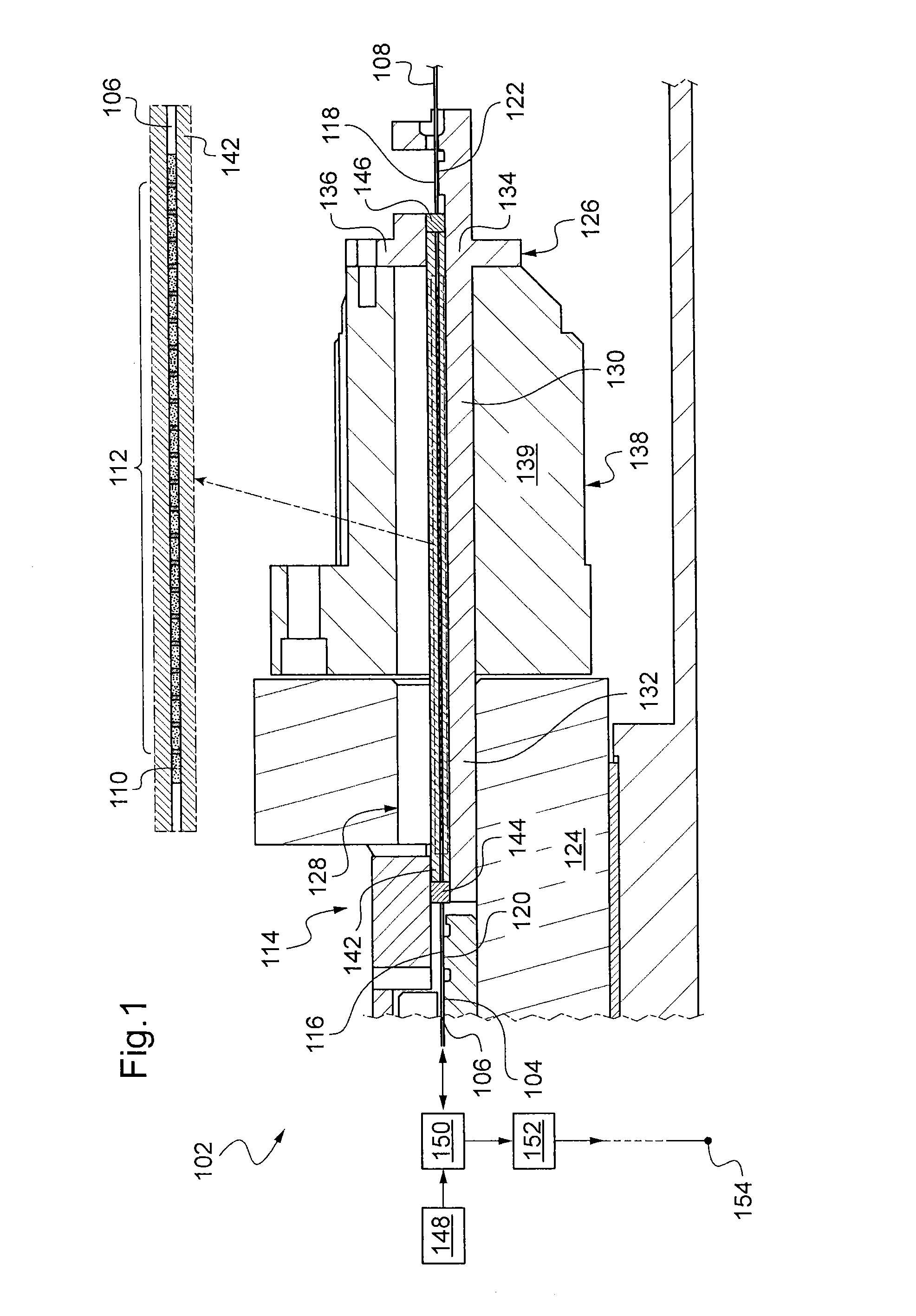
[0031]With reference to FIG. 1, an optical fibre laser 102 implementing the invention will now be described. In the example described, the laser 102 is a longitudinal single-mode laser.

[0032]The laser 102 firstly comprises an optical fibre 104. The optical fibre 104 has, in a manner known per se, a core and cladding around the core, the refractive index of the cladding being lower than that of the core. The core and cladding are encased by a protective sheath. The optical fibre 104 is provided with two ends 106, 108, of which a first 106 is intended to allow light to flow in both directions of propagation: to and from the optical fibre 104. The optical fibre 104 has, between the two ends 106, 108 thereof, a doped section 110 for, in a manner known per se, absorbing at least a portion of the light received by the first end 106 of the optical fibre 104 and emitting light, particularly to said first end 106, the light emitted generally having a continuous wavelength range. The optical ...


PUM

PropertyMeasurementUnit
torsion angleaaaaaaaaaa
wavelengthaaaaaaaaaa

Abstract

The laser comprising an optical fiber having two ends of which a first whereby the light is to be received, and a doped section for absorbing at least part of the light received via the first end and emitting light, the method includes: applying a torsion angle to the optical fiber; supplying light having a pump power at the first end of the optical fiber; checking that the Polarization Extinction Ratio of the light output from the first end of the optical fiber remains greater than a predetermined value throughout a predetermined range of the pump power; and, if the Polarization Extinction Ratio remains greater than the predetermined value throughout the predetermined range of the pump power, attaching the optical fiber to a mechanical mount at two attachment points of the optical fiber situated on either side of the doped section, with the torsion angle applied to the optical fiber.

Description

[0001]The invention relates to a method for manufacturing an optical fibre laser.BACKGROUND OF THE INVENTION[0002]The invention applies more particularly, but not exclusively, to the field of Distributed Feedback Lasers (DFL) or Distributed Bragg Reflectors (DBR), intended to operate at ambient pressure or in a vacuum, as for space applications for example.DESCRIPTION OF THE PRIOR ART[0003]However, some known optical fibre lasers exhibit unstable behaviour characterised by a change over time in the polarisation direction of the light beam at the laser output.[0004]In this way, a solution to this instability problem may be sought.SUMMARY OF THE INVENTION[0005]For this purpose, the invention relates to a method for manufacturing an optical fibre laser comprising an optical fibre having two ends, of which a first whereby the light is to be received, and a doped section for absorbing at least one portion of the light received via the first end and emitting light, the method comprising:[...

Claims


Application Information

Patent Timeline
Patent Type & Authority Patents(United States)
IPC IPC(8): B21D39/03G02B6/42G02B6/26B23P11/00G02B6/00H01S3/102G02B6/32H01S3/10H01S3/04G02B6/032H01S3/067H01S3/0941
CPCH01S3/06704H01S3/102H01S3/0405H01S3/0675H01S3/06712H01S3/09415H01S3/10061Y10T29/49826
Inventor FOURCAULT, WILLIAMCHARRAT, BRUNOLEGER, JEAN-MICHEL
Owner COMMISSARIAT A LENERGIE ATOMIQUE ET AUX ENERGIES ALTERNATIVES
Why Eureka
Try Eureka