Video rendering across a high speed peripheral interconnect bus

a high-speed, peripheral interconnect technology, applied in the field of computing devices, can solve the problems of inability to provide the features or performance of high-performance, graphics processors are nearly as complex as central processors, integrated graphics processors, and by comparison, and can be easily confused with each other, and the integration of graphics components is typically redundant and therefore disabled

Inactive Publication Date: 2008-06-19
ATI TECH INC
View PDF37 Cites 65 Cited by
  • Summary
  • Abstract
  • Description
  • Claims
  • Application Information

AI Technical Summary

Benefits of technology

[0009]In this way the graphics processor may form part of a graphics adapter that need not include a display interface or possibly even a frame buffer. Likewise, the graphics processor may be replaced with a more current graphics processor.

Problems solved by technology

Leading graphics processors are nearly as complex as central processors.
Integrated graphics processors, are by comparison, relatively simple and do not provide the features or performance of the high performance, graphics processors formed on peripheral cards.
In the presence of an add-on peripheral card, integrated graphics components when present, are typically redundant and therefore disabled.

Method used


Image

  • Video rendering across a high speed peripheral interconnect bus
  • Video rendering across a high speed peripheral interconnect bus
  • Video rendering across a high speed peripheral interconnect bus

Examples


first embodiment

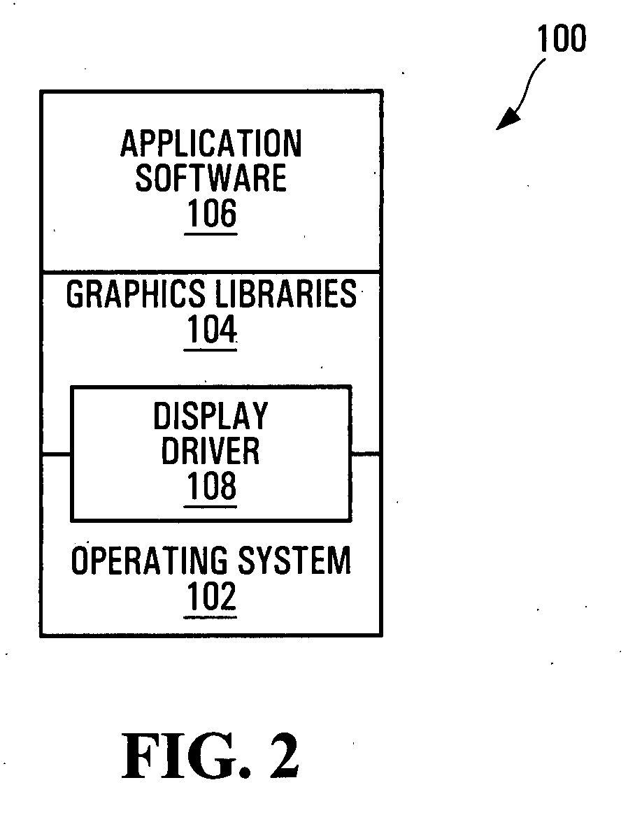
[0061]In a first embodiment, graphics adapter driver software 108 within memory 16 performs steps S500 depicted in FIG. 5A. Specifically, driver software 108 generates commands directing graphics processor 54 to render the secondary adapter buffer 72 of memory 56, in steps S502. These commands are placed in the command queue 57 of adapter 52 and executed by graphics processor 54, in much the same way as commands would be queued in queue 47, as described above. Once the frame is rendered, driver software 108 further generates a command (or commands) causing processor 54 to bit block transfer (BITBLT) the contents of secondary adapter frame buffer 72 within memory 56 in step S504, to that area of memory 16 allocated as frame buffer 46 for graphics adapter 34.

[0062]Display interface 44 of graphics adapter 34, in turn, has been pre-programmed to display the contents of its frame buffer 46 to an interconnected monitor or display at port 48. Conveniently then, images displayed on displays...

second embodiment

[0063]In a second embodiment, steps S600 depicted in FIG. 6A are performed. Initially, front and back frame buffers are allocated within memory 16 of adapter 52. For convenience these are designated as buffers 46a and 46b, and depicted in FIG. 6B. Processor 54 again renders any frame to presented by display interface 44 within secondary adapter frame buffer 72 of memory 56 as described above with reference to step S502, in step S602.

[0064]At the conclusion of rendering a frame for display on device 32, driver software 108 programs graphics processor 54 to bit block transfer (BITBLT) the contents of secondary adapter frame buffer 72 within memory 56, to the then current back buffer within memory 16 for graphics adapter 34 in step S604. Upon completion of the BITBLT, driver programs processor 54 to program registers of display interface 44 to flip the back buffer and front buffer of adapter 34 (i.e. use the back buffer as the front buffer), in step S606. This may be done by directly r...

third embodiment

[0066]Thus, in yet a third embodiment, steps S700 depicted in FIG. 7 may be performed. Again, front and rear buffers 46a, 46b are initially allocated within memory 16 used by adapter 34. Processor 54 again renders images for display at device 32 within buffer 72 of local memory 56, as described above with reference to steps S502 and S602.

[0067]At the completion of rendering a frame for display on display 32, driver software 108 within memory 16 programs graphics processor 54 to bit block transfer (BITBLT) the contents of secondary adapter frame buffer 72 within memory 56, to the then current back buffer within memory 16 of graphics adapter 34 in step S704. Driver software 108 further places a command in the command queue 47 of adapter 34 to flip front and back buffers, in step S706. However, registers of command processor 42 are not updated by driver software 108 to reflect the pending command in command queue 47. Instead, driver software 108 provides a command to graphics processor...


PUM


Abstract

Graphics generated by one graphics processor are transferred across a high speed interconnect bus to a frame buffer. The rendered frames from the frame buffer are presented on a display by way of a display interface in communication with the frame buffer. The display interface of another existing (e.g. integrated) graphics adapter / subsystem may be used to present the rendered frames on an interconnected display.

Description

CROSS-REFERENCE TO RELATED APPLICATIONS[0001]The present application is a continuation-in-part of U.S. patent application Ser. Nos. 11 / 136,483 filed May 24, 2005 and U.S. patent application Ser. No. 11 / 421,005 filed May 30, 2006, the contents of both of which are hereby incorporated by reference.FIELD OF THE INVENTION[0002]The present invention relates generally to computing devices, and more particularly to a computing device including graphics processors interconnected by a high speed peripheral bus.BACKGROUND OF THE INVENTION[0003]In recent years, computer hardware has become increasingly integrated. Computer peripherals are often formed as part of an integrated chipset that cooperates with a central processor. Often, computer audio, graphics adapters and interfaces form part of the integrated chipsets. Such integration reduces costs and size of the computing devices.[0004]At the same time, graphics processors are steadily evolving to provide enhanced performance and features. Le...

Claims


Application Information

Patent Timeline
Patent Type & Authority Applications(United States)
IPC IPC(8): G06F15/16
CPCG06T1/20G09G5/397G09G5/395G09G5/363G06F3/14
Inventor CHENG, JEFFREYLAVIOLETTE, TERRYHUANG, JAMESZABRZYCKI, ROBERTLONG, JASONWENG, XIANGQUANMARINKOVIC, SASAMUMMAH, PHILCHIEN, MINGWEITRESIDDER, MICHAELSALTCHEV, ROUMENXIE, GEORGELITCHMANOV, IOURI
Owner ATI TECH INC
Why Eureka
Try Eureka