

Tone correction table generation method and apparatus
a tone correction and tone technology, applied in the field of color image forming apparatus, can solve the problems of often disabled tone control based only on chromatic value, inability to realize precise tone characteristics, etc., and achieve the effect of satisfying color reproducibility and improving calibration precision
- Summary
- Abstract
- Description
- Claims
- Application Information
AI Technical Summary
Benefits of technology
Problems solved by technology
Method used
Image

Examples
first embodiment
Apparatus Arrangement
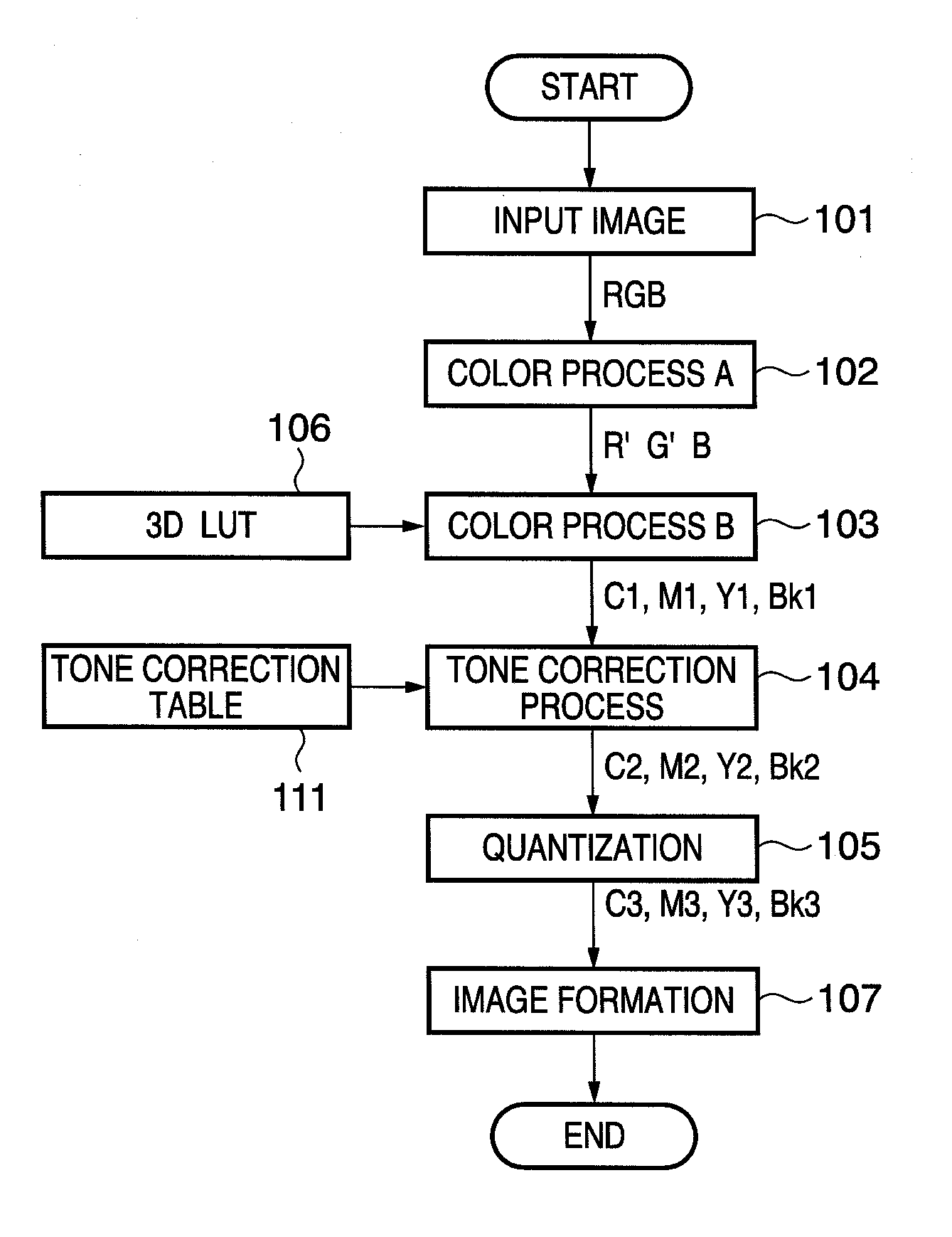
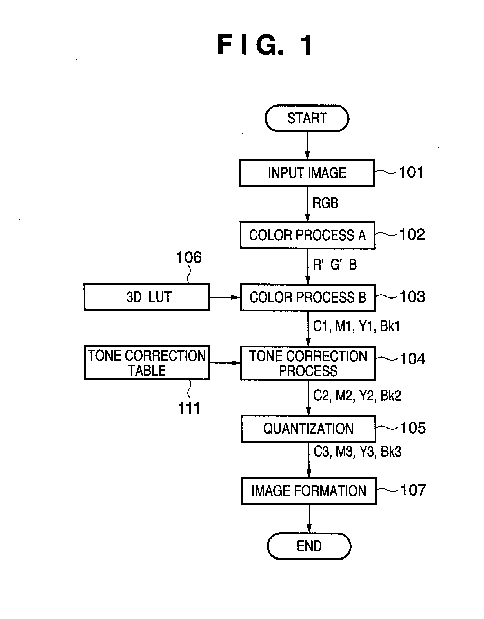
[0038]FIG. 1 is a flowchart showing an example of the processing of an ink-jet printer as an image forming apparatus which is applicable to the present invention. In an image input step 101, R, G, and B original image signals are input from an image input device such as a digital camera, scanner, or the like, or a computer. In a color process A step 102, the input R, G, and B original image signals into R′, G′, and B′ signals. The R′, G′, and B′ signals are R, G, and B data which have undergone conversions for color cast, contrast, and chroma corrections. Or the R′, G′, and B′ signals are R, G, and B data which are converted into an RGB space depending on each device. In a color process B step 103, the R′, G′, and B′ signals are converted into signal values corresponding to respective color inks. The printer of this embodiment forms an image using inks of four component colors Y, M, C, and Bk. Therefore, the converted signals are image signals C1, M1, Y1, and Bk...
second embodiment
[0083]The second embodiment of the present invention will be described in detail hereinafter with reference to the accompanying drawings. The first embodiment has explained the method of generating a tone correction table for Y (yellow), for example, using chromatic values or color difference values, since Y has a small brightness change amount and precise tone reproduction cannot be realized due to the influence of errors. On the other hand, in the above description, if a tone correction table for C (cyan) or M (magenta) is generated using chromatic values as in Y (yellow), the chroma difference between neighboring patches becomes negative as an image signal value increases. For this reason, an inversion of chromatic values occurs with respect to image signal values and a tone correction table for C or M cannot be generated using the chromatic values. Hence, in the above example, since ink colors respectively have different characteristics, the tone correction table generation meth...
third embodiment
[0092]The first and second embodiments have explained the method of determining an optimal generation method of a tone correction table. This embodiment will explain, as an application example, a method of selecting a method of converting a tone correction table for each ink color using the method of determining the tone correction table generation method described in the first and second embodiments, and executing calibration by the selected method.
[0093]FIG. 9 is a flowchart of the processing for selecting a method used in calibration for generating or updating a tone correction table. Tone characteristic targets of the brightness values, chromatic values, and color difference values of C (cyan), M (magenta), Y (yellow), and Bk (black) are set in advance (S901). This target corresponds to desired tone characteristics after calibration, and may be arbitrarily selected values upon execution of calibration, values of a virtual color image forming apparatus, and the like in addition t...
PUM
 Abstract
Description
Claims
Application Information