

Phosphor, light-emitting member, and image display apparatus
a light-emitting member and image-display technology, applied in the direction of discharge tube luminescent screens, discharge tube/lamp details, luminescent compositions, etc., can solve the problems of insufficient performance in both color reproducing range and luminance, and achieve satisfactory color reproducibility, enhance luminance, and expand color reproducing range
- Summary
- Abstract
- Description
- Claims
- Application Information
AI Technical Summary
Benefits of technology
Problems solved by technology
Method used
Image


Examples
example 1
[0045]A phosphor material of the present invention was produced. Strontium sulfide powder (SrS), barium sulfide powder (BaS), gallium sulfide powder (Ga2S3), and europium chloride powder (EuCl3) were used as the material, and the respective powders were mixed using a mortar. The respective materials were weighed to meet the weight ratio of SrS:BaS:Ga2S3:EuCl3≅0.44:0.09:1:0.03 so that the host material has a composition represented by Ba0.1Sr0.9Ga2S4. The concentration of Eu was three atomic percent with respect to the molar concentration of Sr+Ba.
[0046]The powder was then put into a crucible made of alumina, arranged in an atmosphere of hydrogen sulfide gas diluted with argon to 2%, and subjected to a crystallizing process in the atmosphere of 1000° C. for two hours. The composition ratio of the powder of the phosphor material produced in the above manner was analyzed by X-ray fluorescent. As a result, it was confirmed to have obtained the phosphor material with the composition rati...
example 2
[0048]A phosphor material different in composition ratio was produced through the same process as in Example 1. Strontium sulfide powder (SrS), barium sulfide powder (BaS), gallium sulfide powder (Ga2S3), and europium chloride powder (EuCl3) were used as the material. The materials were weighed to meet the weight ration of SrS:BaS:Ga2S3:EuCl3≅0.30:0.28:1:0.03 so that the host material has a composition represented by Ba0.4Sr0.6Ga2S4.
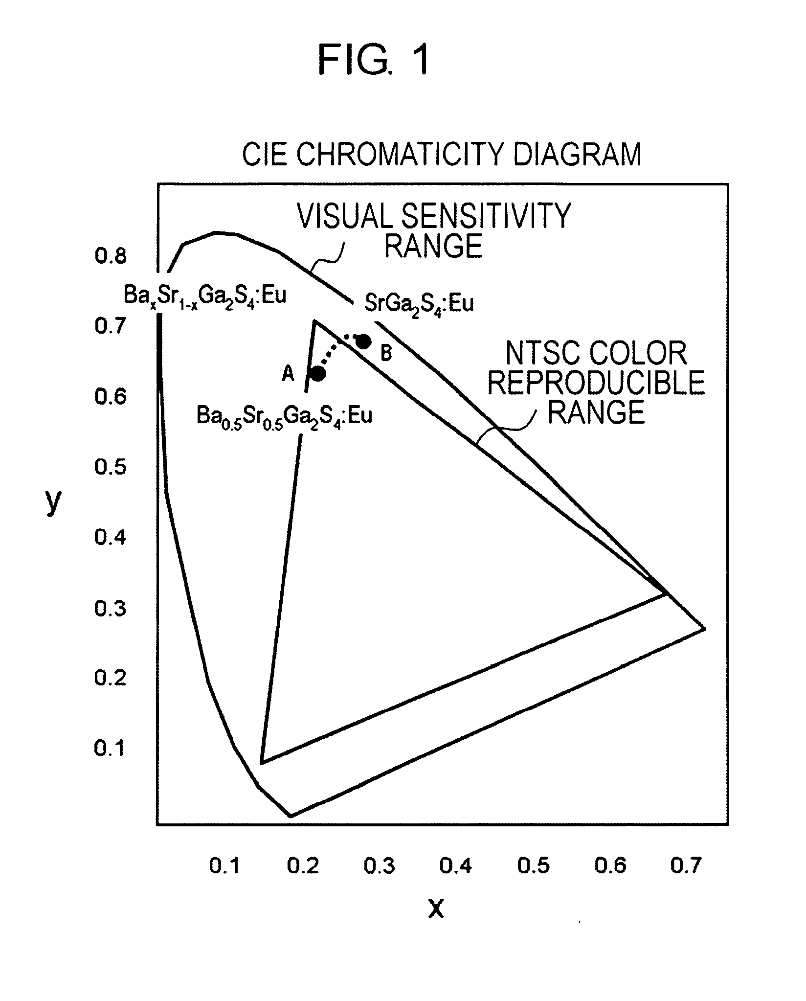
[0049]An evaluation was conducted on the light-emitting characteristic of the phosphor material obtained by the above process. Luminance obtained by irradiating 0.1 gram of powder with electron beam having a current density of 1 mA / cm2 was 363 cd / m2. This luminance is approximately 1.04 times as high as that of the SrGa2S4:Eu phosphor. The CIE chromaticity coordinate was (x, y)=(0.239, 0.663).
example 3
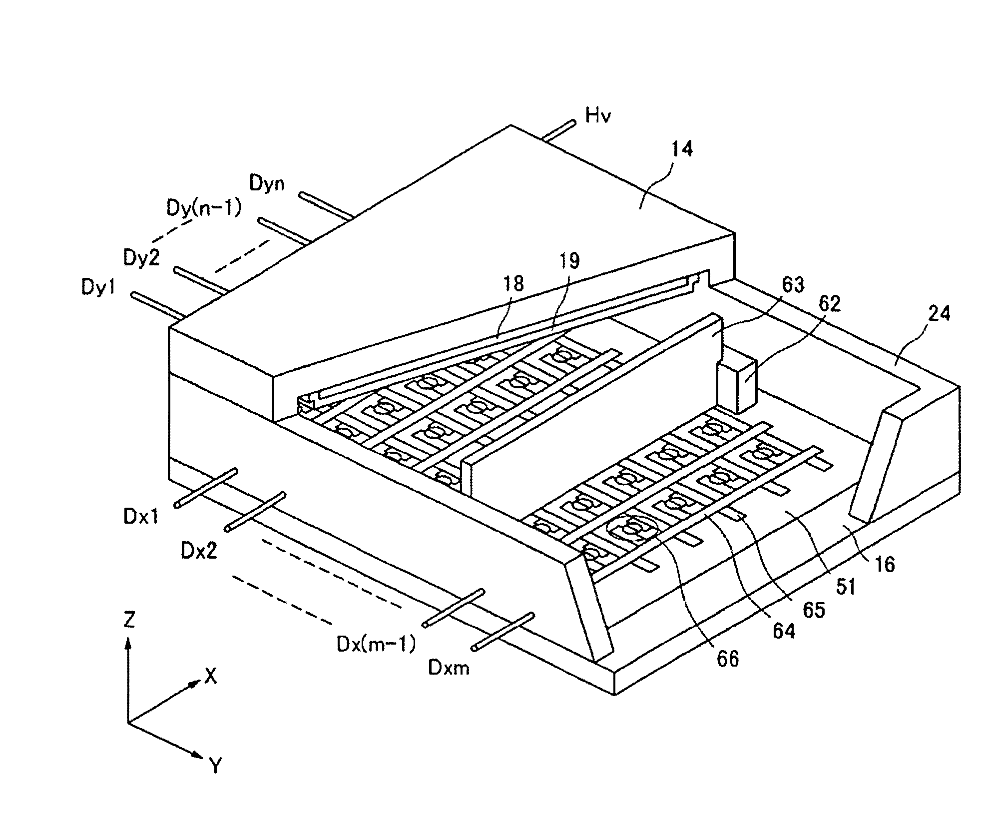
[0050]An image display apparatus was produced using the phosphor material produced in Example 1. The image display apparatus of the present example is the FED of FIG. 3 equipped with the device whose configuration is shown in FIG. 4.
[0051]First, a method of producing a rear plate (electron source substrate) 20 will be described.
[0052]A 200 nm aluminum as the cathode electrode 9 was deposited on the glass substrate 8 by the sputtering method. A 600 nm of silicon dioxide was then deposited as the insulating layer 10 by the CVD method, and 100 nm of titanium film was deposited as the gate electrode 11 by the sputtering method.
[0053]The opening 12 with a diameter of 1 μm was formed in the gate electrode 11 and the insulating layer 10 by photolithography and etching process.
[0054]The substrate passed through the above production process was arranged in the sputtering device, the air in the device was evacuated and then molybdenum was deposited obliquely to form the electron-emitting port...
PUM
| Property | Measurement | Unit |
|---|---|---|
| light emission peak wavelength | aaaaa | aaaaa |
| light emission peak wavelength | aaaaa | aaaaa |
| temperature | aaaaa | aaaaa |
Abstract
Description
Claims
Application Information