Elevator with two elevator cars disposed one above the other in a shaft

Inactive Publication Date: 2008-06-26
INVENTIO AG
View PDF8 Cites 19 Cited by
  • Summary
  • Abstract
  • Description
  • Claims
  • Application Information

AI Technical Summary

Benefits of technology

[0007]The task of the present invention is to further improve the arrangement of eleva

Problems solved by technology

Such an arrangement of the drives

Method used


Image

  • Elevator with two elevator cars disposed one above the other in a shaft
  • Elevator with two elevator cars disposed one above the other in a shaft
  • Elevator with two elevator cars disposed one above the other in a shaft

Examples


Embodiment Construction

[0033]The U.S. provisional patent application Ser. No. 60 / 871,517 filed Dec. 22, 2006 is hereby incorporated herein by reference.

[0034]The following detailed description and appended drawings describe and illustrate various exemplary embodiments of the invention. The description and drawings serve to enable one skilled in the art to make and use the invention, and are not intended to limit the scope of the invention in any manner. In respect of the methods disclosed, the steps presented are exemplary in nature, and thus, the order of the steps is not necessary or critical.

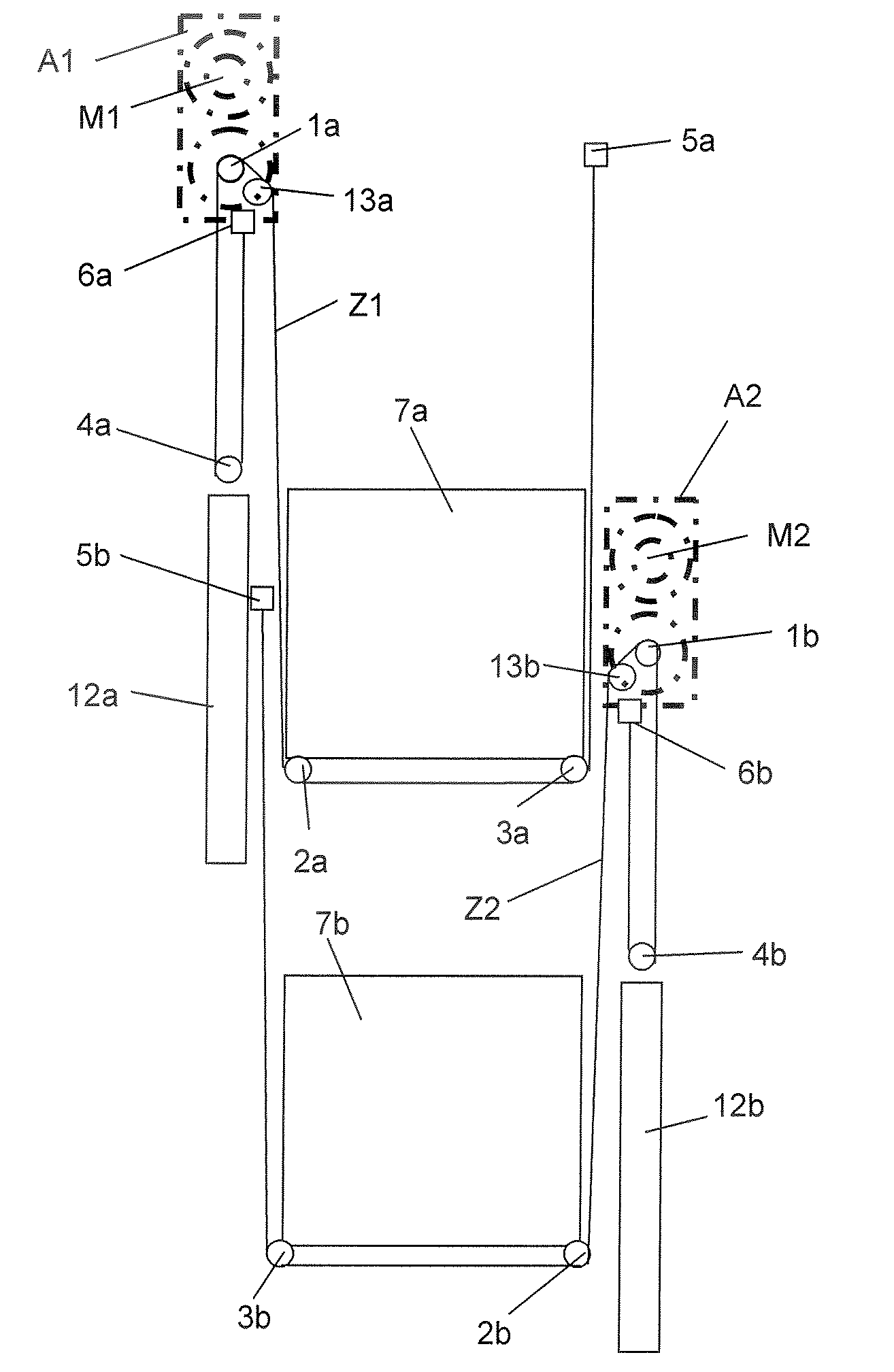
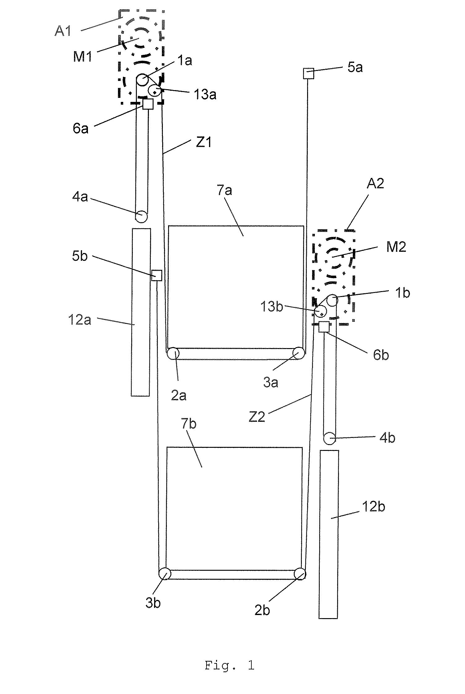
[0035]FIG. 1 shows an elevator with at least two elevator cars 7a, 7b, which each have an associated drive A1, A2 and are movable independently of one another in a vertical direction. The drives A1, A2 are positioned laterally at first and second shaft walls. The first and second shaft walls are those mutually opposite shaft walls not having shaft doors. In that case the drives A1, A2 are disposed in alternation on...


PUM


Abstract

An elevator includes at least two elevator cars which are disposed one above the other and vertically movable in a shaft independently of one another and which each have an associated drive with at least one motor and at least one drive pulley, an associated counterweight and at least one associated tension device. One of the drives is fixed to a first shaft wall and the other drive is fixed to an opposite second shaft wall. The drives can be passed by the elevator cars, wherein the drives are arranged vertically above the associated drive pulleys.

Description

CROSS-REFERENCE TO RELATED APPLICATION[0001]This application claims the benefit of U.S. provisional patent application Ser. No. 60 / 871,517 filed Dec. 22, 2006.FIELD OF THE INVENTION[0002]The present invention relates to an elevator with at least two elevator cars which are arranged one above the other and vertically movable in a shaft.BACKGROUND OF THE INVENTION[0003]An elevator usually comprises an elevator car, which is vertically movable in a shaft and receives passengers in order to transport these to a desired floor of a building. In order to be able to look after this task the elevator usually has at least the following elevator components: a drive with a motor and a drive pulley, deflecting rollers, tension means, a counterweight, as well as a respective pair of guide rails for guidance of the elevator car and the counterweight.[0004]In that case the motor produces the power required for transport of the passengers present in the elevator car. An electric motor usually provid...

Claims


Application Information

Patent Timeline
IPC IPC(8): B66B9/00
CPCB66B11/0095B66B11/0045B66B7/00B66B11/02B66B11/04
Inventor KOCHER, HANS
Owner INVENTIO AG
Why Eureka
Try Eureka