Articles, systems, and methods for suppressing noise and/or vibrations in hotel/motel doors

a technology for hotel/motel doors and noise suppression, applied in the field of sliding door locks, can solve the problem of a single decibel sound, and achieve the effect of preventing the production of harsh loud sound

Inactive Publication Date: 2008-06-26
FIDALI WLODZIMIERZ +1
View PDF0 Cites 4 Cited by
  • Summary
  • Abstract
  • Description
  • Claims
  • Application Information

AI Technical Summary

Benefits of technology

[0012]It is therefore an object of this invention to prevent the production of a harsh loud sound upon contact between a door and a door guard attached to a frame of the door when releasing the door.
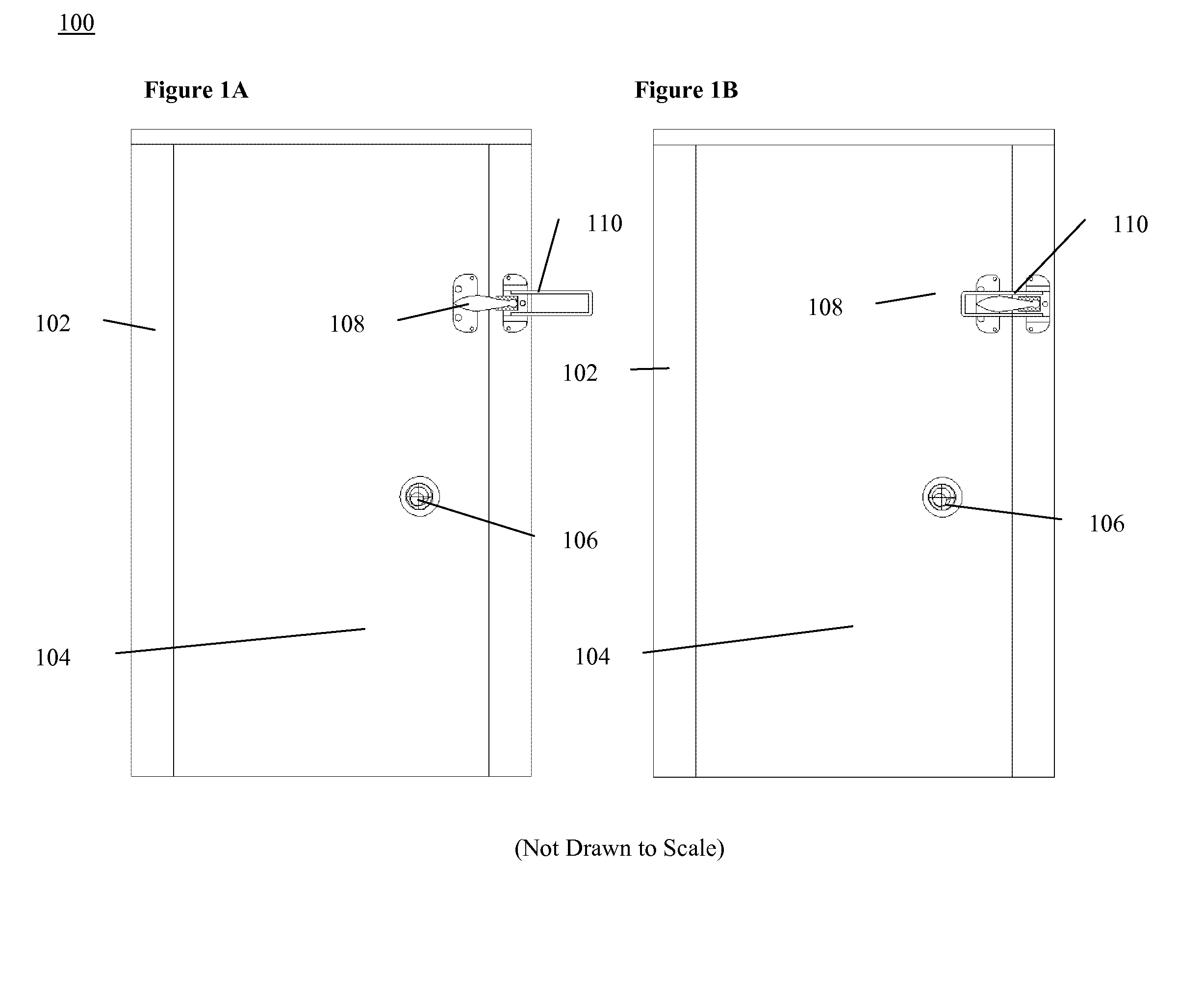
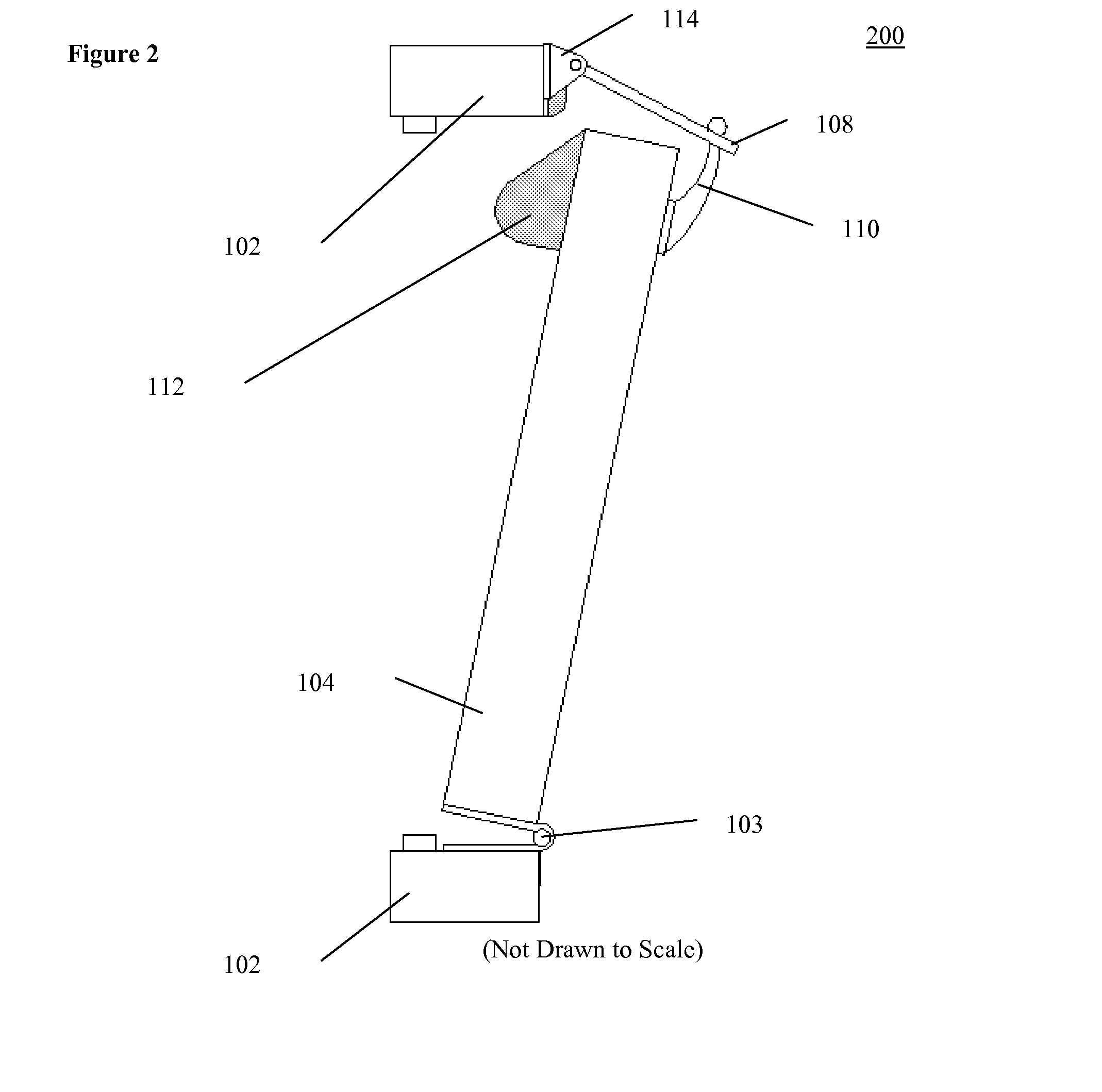
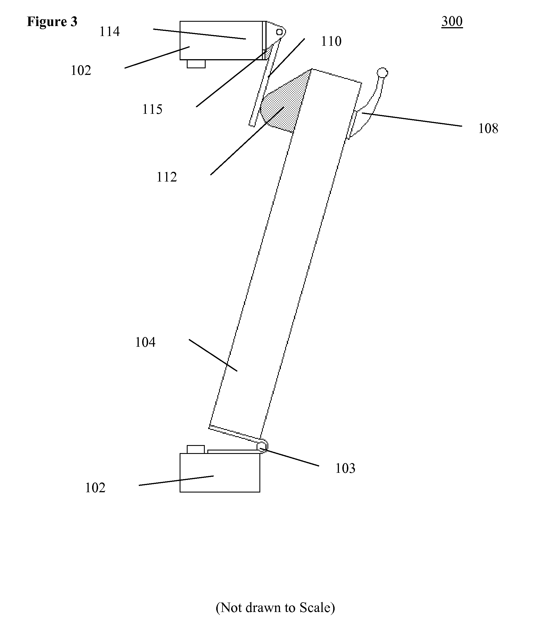
[0013]The present invention relates to a door guard setup where, when the door guard is released and the door swings closed, a slamming sound and vibrations occurs. To remedy this, two articles are attached, one article to the door and another article to the door frame. When the door guard is released causing the door to close, the attached articles reduces the sound and vibration of the door, resulting in a sound of a single decibel. Therefore, a simple and cost effective device is easily installed and easily maintained.
[0014]Accordingly, an embodiment of the present invention is an article to be attached to a door for suppressing sound when the door strikes a door latch. This article includes a hook element adapted to receive a latch member of the door latch and attached to an inside surface of the door; and a damping element, composed of a sound dampening material, attached to an outside surface of the door. The sound dampening material could be a rubber, or any other material capable of damping sound and / or reducing vibrations.

Problems solved by technology

When the door guard is released causing the door to close, the attached articles reduces the sound and vibration of the door, resulting in a sound of a single decibel.

Method used


Image

  • Articles, systems, and methods for suppressing noise and/or vibrations in hotel/motel doors
  • Articles, systems, and methods for suppressing noise and/or vibrations in hotel/motel doors
  • Articles, systems, and methods for suppressing noise and/or vibrations in hotel/motel doors

Examples


Embodiment Construction

[0045]It is noted that in this disclosure and particularly in the claims and / or paragraphs, terms such as “comprises,”“comprised,”“comprising,” and the like can have the meaning attributed to it in U.S. patent law; that is, they can mean “includes,”“included,”“including,” and the like, and allow for elements not explicitly recited. Terms such as “consisting essentially of” and “consists essentially of” have the meaning ascribed to them in U.S. patent law; that is, they allow for elements not explicitly recited, but exclude elements that are found in the prior art or that affect a basic or novel characteristic of the invention. These and other embodiments are disclosed or are apparent from and encompassed by, the following description.

[0046]In this respect, before explaining at least one embodiment of the invention in detail, it is to be understood that the invention is not limited in its application to the details of construction and to the arrangements of the components set forth i...


PUM


Abstract

A door guard for hotel / motel doors comprises two articles, one article to be attached to a door, and another article to be attached to a door frame. One article is attached to the door, including a hook element adapted to receive a latch member of the door guard and attached to an inside surface of the door; and a damping element, composed of a sound dampening material, attached to an outside surface of the door. Another article is attached to the door frame, including a hinge element for connecting the article to the door frame; and a latch member pivotally connected to the hinge element. Another sound damping element, also composed of a sound dampening material, is disposed between the hinge element and the latch member. When the door guard is released and the door closes, the attached articles reduce the sound and / or vibrations, which are disturbing to hotel / motel guests, that occur when the closing door impacts the door guard and door frame.

Description

REFERENCES TO RELATED APPLICATIONS[0001]This application is a continuation application and claims priority from co-pending U.S. application Ser. No. 11 / 610,843, filed on Dec. 14, 2006, Notice of Allowance mailed on Jan. 9, 2008 and issued on ______, the entirety of which is hereby incorporated by reference herein.FIELD OF THE INVENTION[0002]The present invention relates to a slide door lock used for hotel and motel doors. More particularly, the present invention relates to an article attached to a door and door frame for reducing the noise, friction, and vibrations between the hinge, door, and latch member of a door guard system. The present invention is primarily intended for slide locks used with either hotel or motel doors, but is not limited to such doors.BACKGROUND OF THE INVENTION[0003]This invention relates to hotel and motel door guards, and more particularly to a noiseless apparatus best adapted for use with doors of hotels and motels which are concerned with the comfort of...

Claims


Application Information

Patent Timeline
Patent Type & Authority Applications(United States)
IPC IPC(8): E05C19/00E04B1/82
CPCE05C17/166E05F5/02E05F5/04Y10T16/61Y10S292/15Y10S292/56E05F2005/046E05Y2900/132Y10T292/28Y10T292/34Y10T292/03
Inventor FIDALI, WLODZIMIERZLOGAN, ROBERT T.
Owner FIDALI WLODZIMIERZ
Why Eureka
Try Eureka