Relay Device Using Conductive Fluid

Inactive Publication Date: 2008-06-26
MATSUSHITA ELECTRIC WORKS LTD
View PDF14 Cites 5 Cited by
  • Summary
  • Abstract
  • Description
  • Claims
  • Application Information

AI Technical Summary

Benefits of technology

[0005]A primary concern of the present invention is to provide a relay device using a conductive fluid, which has advantages of excellent switching response, easiness of downsizing and stable relay characteristics, as compared with the conventional relay device using the heating means.

Problems solved by technology

However, due to a delay time required to increase the internal pressure of the chamber after the activation of the hater, there is room for improvement in switching response.
However, since it is needed to heat the driving fluid 70N, the switching response becomes a problem, as in the case described above.

Method used


Image

  • Relay Device Using Conductive Fluid
  • Relay Device Using Conductive Fluid
  • Relay Device Using Conductive Fluid

Examples


first embodiment

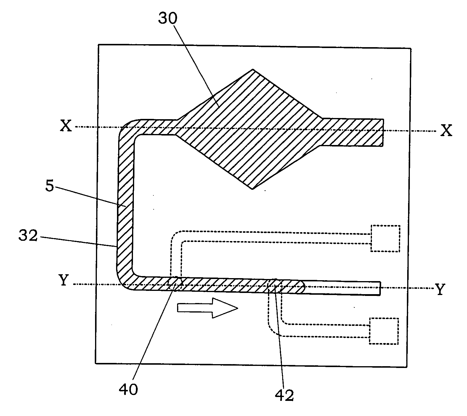
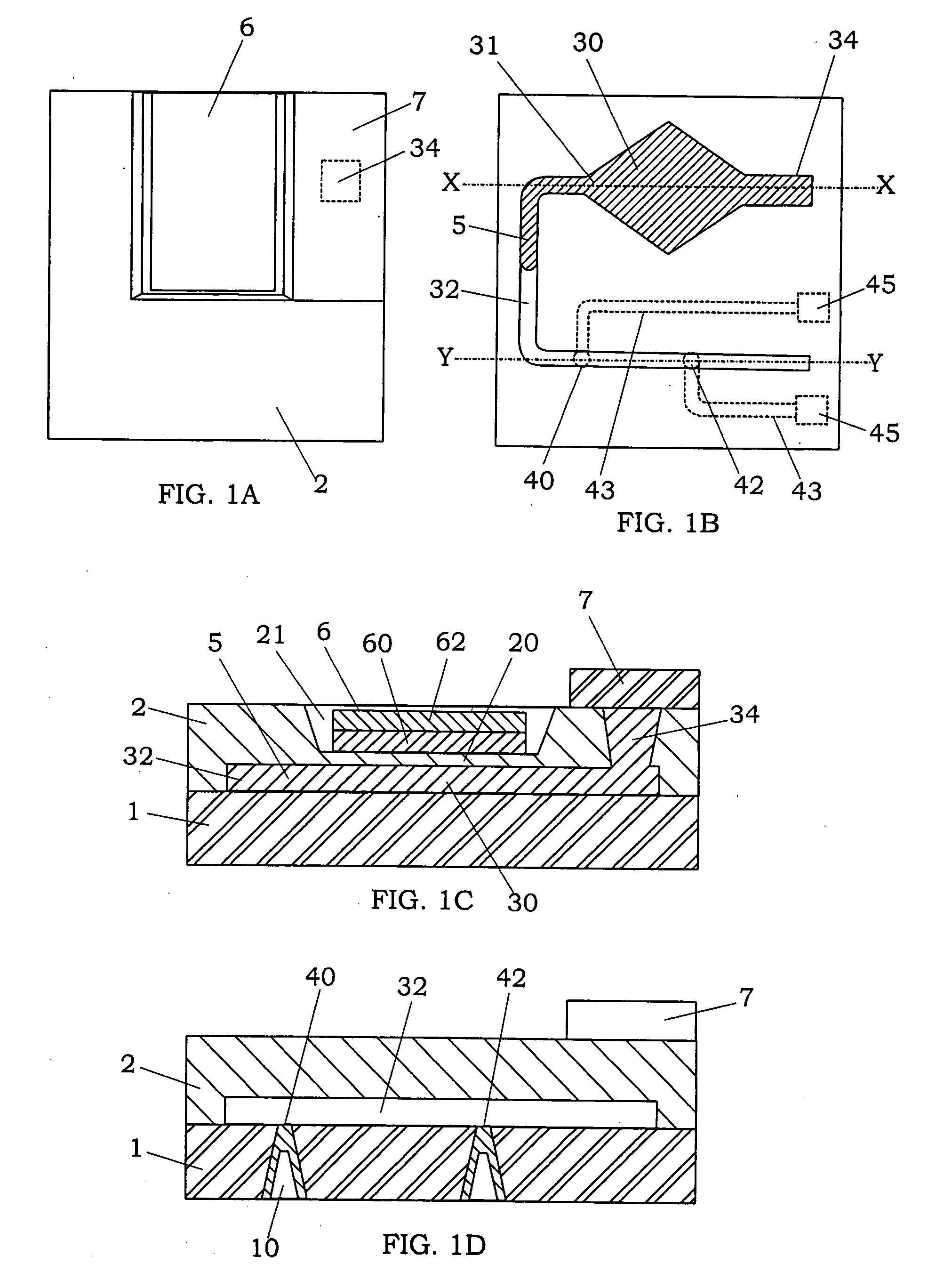
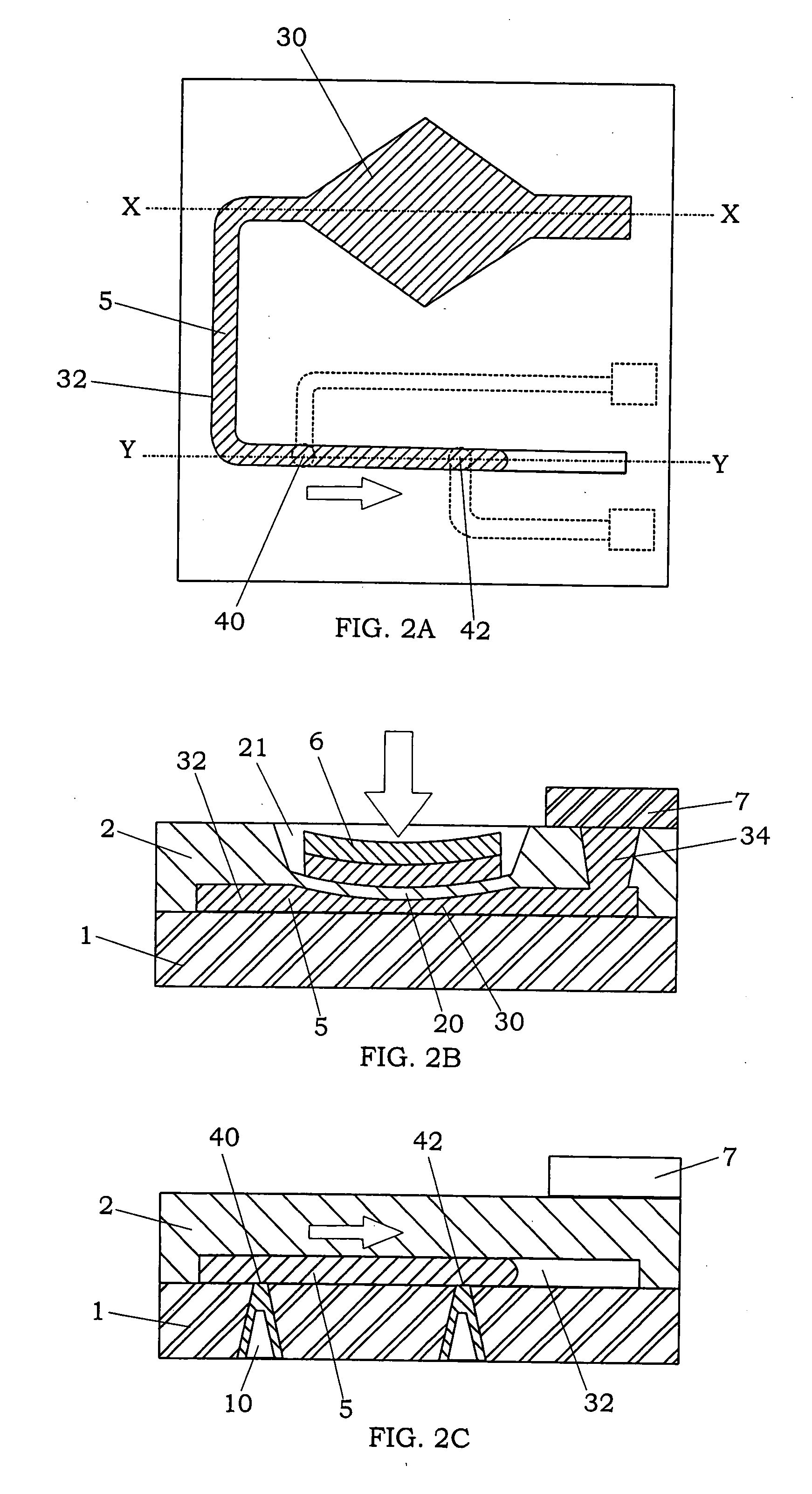
[0049]As shown in FIGS. 1A to 1D, a relay device of the first embodiment of the present invention is mainly provided with a laminate, which is formed by anodic bonding between an insulating substrate 1 and a semiconductor substrate 2 so as to have an interior space (fluid chamber) comprised of a fluid storage portion 30, in which a conductive fluid 5 is injected, and a fluid channel 32, a pair of contacts (40, 42) exposed to the fluid channel, a diaphragm portion 20 formed in the semiconductor substrate and facing the fluid storage portion 30, and an actuator 6 configured to elastically deform the diaphragm portion 20.

[0050]The insulating substrate 1 for the laminate is not limited, and a substrate having insulating property is available. For example, the insulating substrate 1 can be made of a glass material or an insulating resin material. In the present embodiment, a glass substrate is used as the insulating substrate 1. The insulating substrate 1 has a plurality of through holes...

second embodiment

[0068]A relay device of the present embodiment is characterized in that a fluid storage portion has a substantially circular shape in its plan view, and a pair of contacts are disposed in the fluid storage portion without the formation of a fluid channel. That is, this relay device is substantially the same as the relay device of the first embodiment except for the following features. Therefore, the duplicate explanation of common parts will be omitted.

[0069]In the relay device of the present embodiment, as shown in FIGS. 14A to 14C, the fluid storage portion 30 has a substantially circular shape in its plan view, and the pair of the contacts (40, 42) are formed on the insulating substrate 1 to be exposed to the fluid storage portion 30. The conductive fluid 5 is injected in the fluid storage portion 30 to always contact only one of the contacts (40) in the rest state of the actuator 6. When the actuator is activated under this condition, the circular diaphragm portion 20 is elastic...

third embodiment

[0071]According to the basic concept of the first embodiment, a relay device of the present embodiment is characterized by simultaneously controlling a pair of contacts configured in a normally-open state and a pair of contacts configured in a normally-close state by operation of an actuator. That is, this relay device is substantially the same as the relay device of the first embodiment except for the following features. Therefore, the duplicate explanation of common parts will be omitted.

[0072]As shown in FIGS. 16A and 16B, the relay device of the present embodiment has an interior space, which is comprised of a fluid storage portion 30 that the diaphragm portion 20 faces, which is configured to accommodate a conductive fluid 5 therein, a second fluid storage portion 90 formed way from the fluid storage portion 30 to accommodate the conductive fluid 5 therein, and a fluid channel 32 coupling between the fluid storage portion 30 and the second fluid storage portion 90. A pair of co...


PUM


Abstract

A relay device using a conductive fluid and having excellent switching response is provided. This relay device mainly comprises a laminate having an interior space, and formed by bonding a semiconductor substrate to an insulating substrate, at least two contacts exposed to the interior space, a diaphragm portion facing the interior space, a conductive fluid sealed in the interior space, and an actuator for elastically deforming the diaphragm portion. By forming the diaphragm portion on the semiconductor substrate, it is possible to reduce a driving force of the actuator needed to elastically deform the diaphragm portion, and obtain a volume change of the interior space with good response. This volume change causes a positional displacement of the conductive fluid in the interior space, thereby forming a conductive state or a non-conductive sate between the contacts.

Description

TECHNICAL FIELD[0001]The present invention relates to a relay device for opening and closing between contacts by use of a conductive fluid.BACKGROUND ART[0002]In recent years, a relay device for opening and closing between contacts by use of a conductive fluid has attracted a lot of interest due to its advantages such as high reliability, low contact resistance, prevention of arc discharge and downsizing, as compared with a conventional relay device.[0003]For example, Japanese Patent Early Publication No. 9-161640 discloses a thermal-driven micro relay device using a conductive fluid such as mercury and germanium. As shown in FIG. 21, this micro relay device is mainly formed with a pair of chambers (10M, 40M), heaters (12M, 42M) disposed in the respective chambers, a channel 20M coupling between the chambers, a liquid metal 50M injected in the channel 20M, a pair of electrodes (30M, 32M) located at a side near the chamber 10M and exposed to the channel 20M, and a pair of electrodes ...

Claims


Application Information

Patent Timeline
IPC IPC(8): H01H29/00
CPCH01H29/00H01H2057/006H01H2029/008H01H29/004H01H29/02
Inventor YOKOYAMA, KOJIUOTOME, RIICHIFURUKUBO, EIICHIKAKIMOTO, KATSUMIMESHII, RYOSUKEUEDA, HIDEKIKOBAYASHI, MASAKAZU
Owner MATSUSHITA ELECTRIC WORKS LTD
Why Eureka
Try Eureka