Image sensing apparatus with electronic shutter function and mechanical shutter function, and image sensing method

a technology of electronic shutter and mechanical shutter, which is applied in the field of image sensing apparatus with electronic shutter function and mechanical shutter function, and image sensing method, can solve the problems of large shutter, high cost, and mechanical shutter being difficult to drive at a high speed, and achieve the effect of preventing image degradation

Inactive Publication Date: 2008-06-26
CANON KK
View PDF10 Cites 8 Cited by
  • Summary
  • Abstract
  • Description
  • Claims
  • Application Information

AI Technical Summary

Benefits of technology

[0009]The present invention has been made in consideration of the above situation, and has as its first object to provide an image sensing method and image sensing apparatus capable of preventing degradation of an image caused by smear of an image sensing element.
[0010]It is the second object of the present invention to provide an image sensing method and image sensing apparatus capable of preventing the user from feeling incompatibility in switching a photographing sequence.
[0011]It is the third object of the present invention to provide an image sensing method and image sensing apparatus capable of achieving a stable frame speed in sequential shooting and an increase in speed without measuring and adjusting variations in exposure time caused by the mechanical delay of a mechanical shutter.

Problems solved by technology

The shutter itself becomes a complicated mechanism, resulting in a large shutter and high cost.
The mechanical shutter is technically difficult to drive at a high speed (e.g., 1 / 16,000 sec or more).
However, since the next operation starts upon the end of each operation, the time taken for a photographing sequence per frame is prolonged.
This adjustment is done for each electronic camera, which increases the time taken to assemble and adjust the electronic camera, and increases the cost.
This is inconvenient for a user who uses a plurality of electronic cameras because photographs taken by releasing the shutters of the electronic cameras become different.

Method used


Image

  • Image sensing apparatus with electronic shutter function and mechanical shutter function, and image sensing method
  • Image sensing apparatus with electronic shutter function and mechanical shutter function, and image sensing method
  • Image sensing apparatus with electronic shutter function and mechanical shutter function, and image sensing method

Examples


Embodiment Construction

[0026]A preferred embodiment of the present invention will be described in detail in accordance with the accompanying drawings.

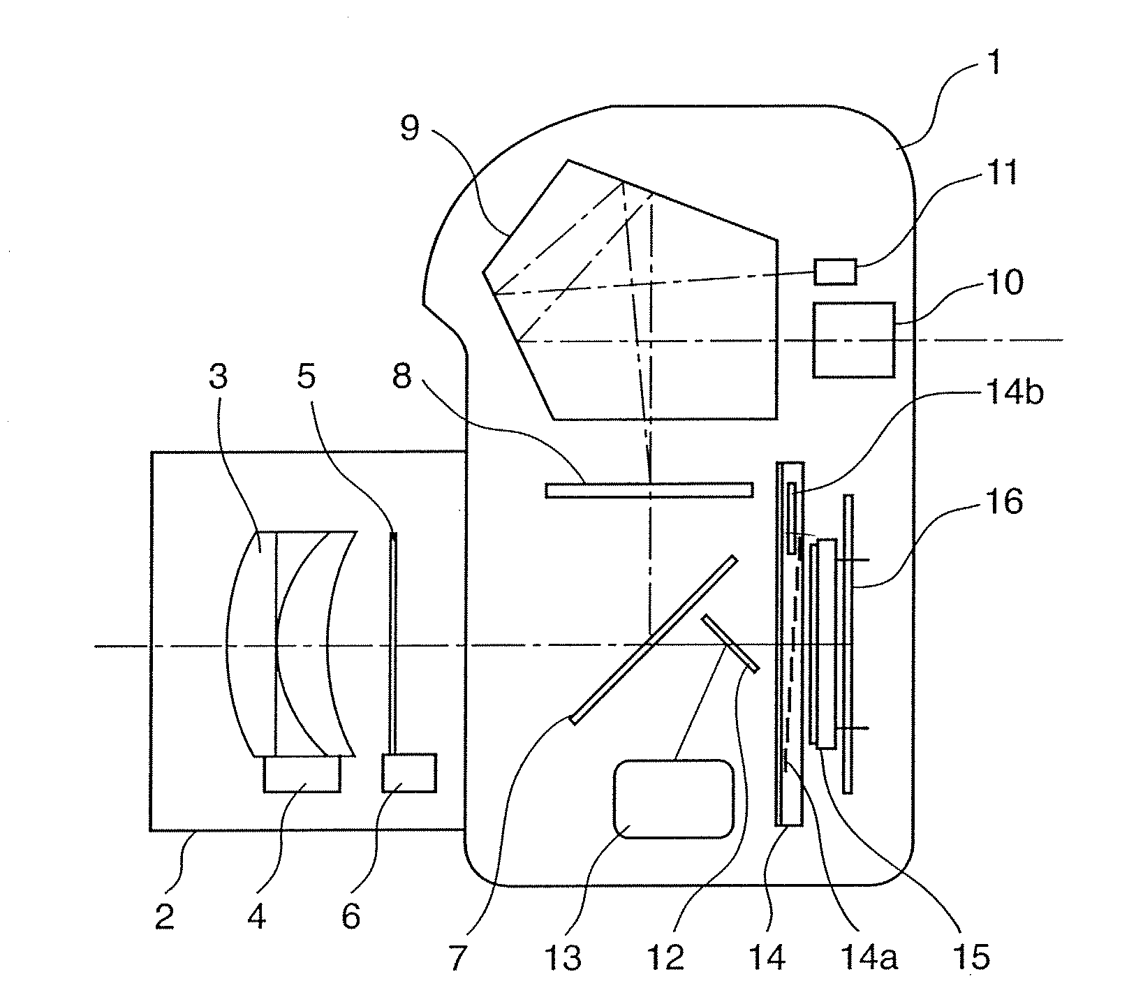
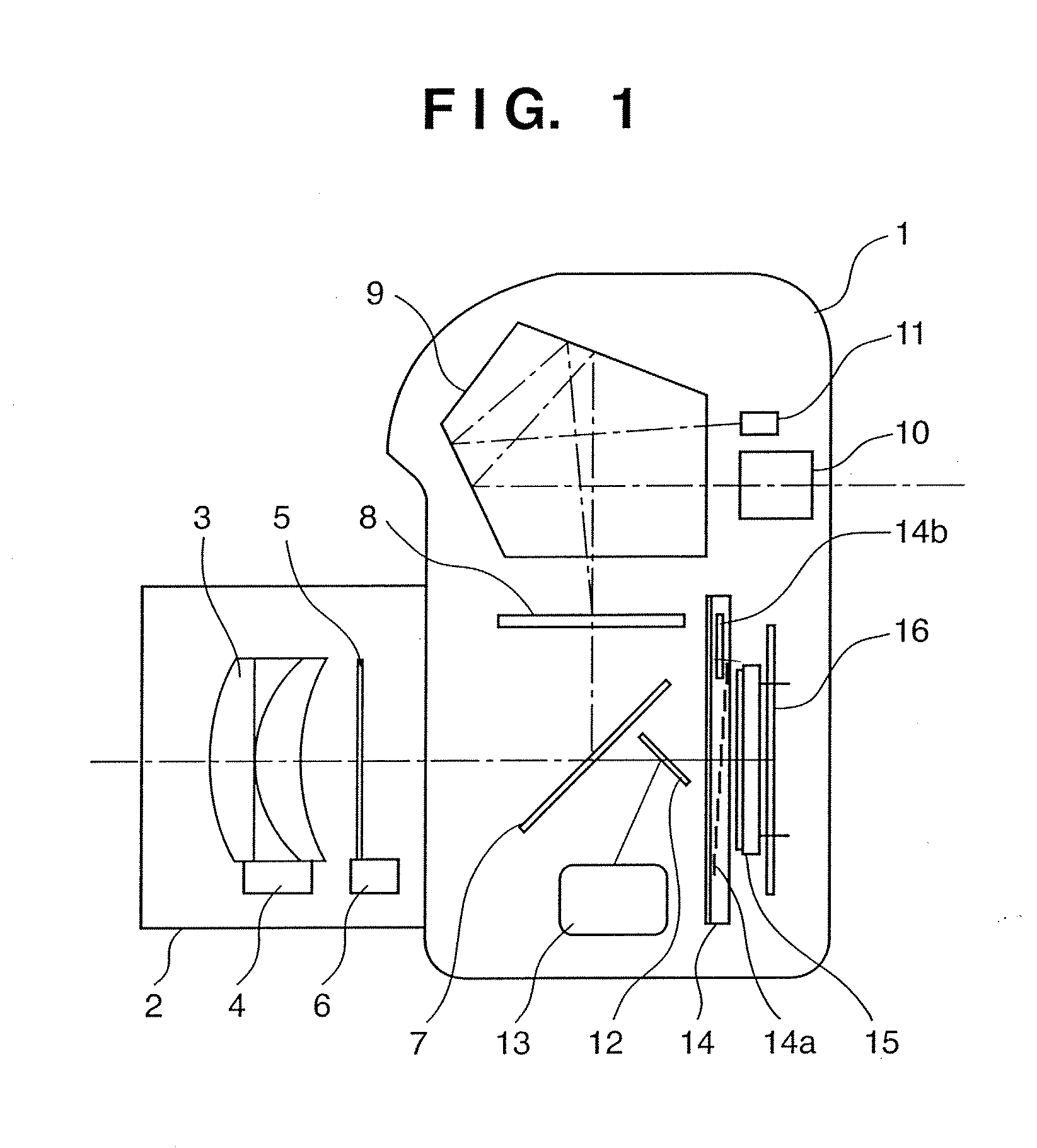
[0027]FIG. 1 is a sectional side view showing the structure of an electronic camera as an image sensing apparatus according to the embodiment. In FIG. 1, reference numeral 1 denotes an electronic camera main body; and 2, a photographing lens for forming an object image on an imaging plane. The photographing lens 2 is detachably attached to the electronic camera main body 1. The photographing lens 2 has an imaging lens 3 for forming an object image on an imaging plane, and a lens driving device 4 for driving the imaging lens 3. Further, the photographing lens 2 includes aperture blades 5 for controlling exposure, and an aperture driving device 6 for driving the aperture blades 5.

[0028]The imaging lens 3 is simplified in FIG. 1, but is formed from one or a plurality of lenses. The imaging lens 3 may be a single-focal-length (fixed-focus) lens or a variable-foc...


PUM


Abstract

An image sensing apparatus having an electronic shutter for controlling the charge accumulation time of an image sensing element and a mechanical shutter for releasing / shielding an optical path to the image sensing element includes an electronic shutter mode of controlling the image sensing time mainly by the electronic shutter and a mechanical shutter mode of controlling the image sensing time mainly by the mechanical shutter. In the electronic shutter mode, the operations of the electronic and mechanical shutters are controlled to overlap each other, and a charge reading period of the image sensing element and part of a release operation period of the mechanical shutter are controlled to overlap each other.

Description

[0001]This application is a continuation of prior application Ser. No. 11 / 109,641, filed Dec. 5, 2001, which claims priority under 35 U.S.C. §120. This application claims a benefit of priority based on Japanese Patent Application No. 2000-371959, filed on Dec. 6, 2000, which is hereby incorporated by reference herein in its entirety as if fully set forth herein.FIELD OF THE INVENTION[0002]The present invention relates to an image sensing method and image sensing apparatus and, more particularly, to an image sensing apparatus with an electronic shutter function and mechanical shutter function and an image sensing method.BACKGROUND OF THE INVENTION[0003]An electronic camera for capturing an image by using an image sensing element such as a CCD (Charge-Coupled Device) for converting light incoming through a photographing lens has an electronic shutter function of controlling the image sensing time by controlling the imaging sensing operation time for receiving light which forms an imag...

Claims


Application Information

Patent Timeline
Patent Type & Authority Applications(United States)
IPC IPC(8): H04N5/335G03B7/093G03B9/08G03B9/36G03B17/02G03B19/02H04N5/235H04N5/353H04N5/359H04N5/372H04N5/378
CPCH04N5/2353H04N5/2351H04N23/71H04N23/73
Inventor MATSUMOTO, TOSHIO
Owner CANON KK
Why Eureka
Try Eureka