Imaging system and method for providing extended depth of focus, range extraction and super resolved imaging

Inactive Publication Date: 2008-06-26
BRIEN HOLDEN VISION INST (AU)
View PDF5 Cites 29 Cited by
  • Summary
  • Abstract
  • Description
  • Claims
  • Application Information

AI Technical Summary

Problems solved by technology

The resolving power or the minimum separation between two points which can be resolved is limited by the

Method used


Image

  • Imaging system and method for providing extended depth of focus, range extraction and super resolved imaging
  • Imaging system and method for providing extended depth of focus, range extraction and super resolved imaging
  • Imaging system and method for providing extended depth of focus, range extraction and super resolved imaging

Examples


Embodiment Construction

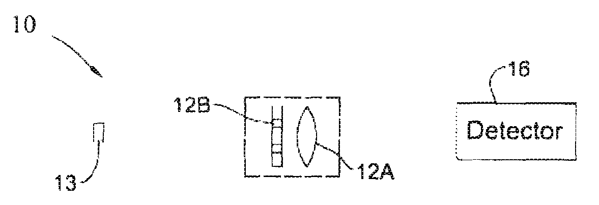
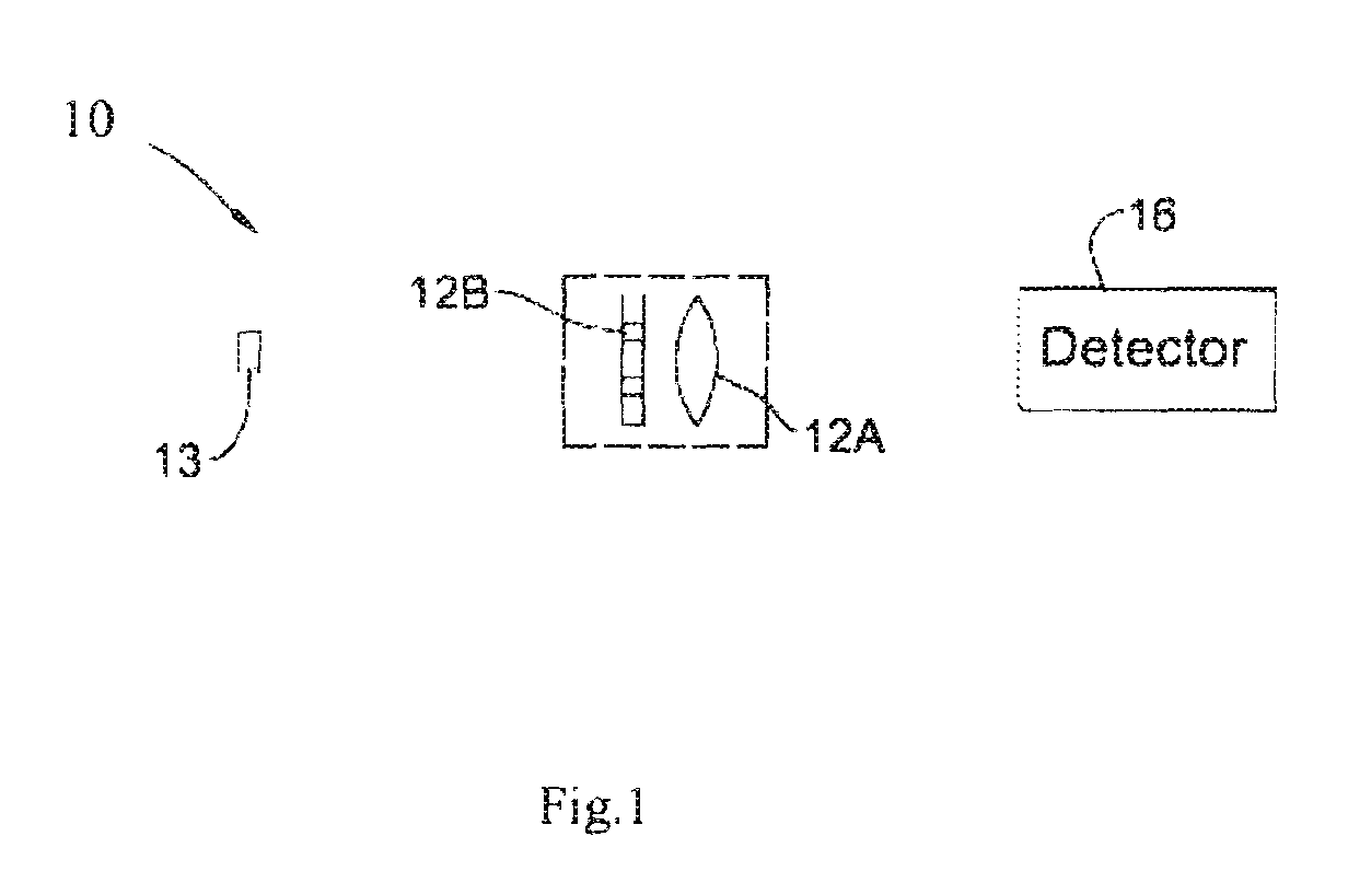
[0046]Reference is made to FIG. 1, schematically illustrating an example of an imaging system 10 configured and operable according to the invention. The imaging system 10 is associated with an object 13 to be imaged, and includes an imaging lens arrangement 12, and a light detector unit 16 associated with a control unit 18. The lens arrangement 12 includes a tensing element 12A and an optical element of random-phase aperture coding 12B. The imaging lens arrangement 12 (lensing element and random-phase aperture coding element) and the light detector unit 16 are preferably optically aligned and stationary mounted. The optical element 12B is configured as a random-phase aperture having phase-affecting pattern of transition regions. Preferably, as shown in the present example, the mask 12B is a separate element attached to the imaging lens or located close to the entrance / exit pupil thereof. Alternatively, the mask 12B may be implemented integral with the lens, namely as a pattern on th...


PUM


Abstract

An imaging system is presented for imaging objects within a field of view of the system. The imaging system comprises an imaging lens arrangement, a light detector unit at a certain distance from the imaging lens arrangement, and a control unit connectable to the output of the detection unit. The imaging lens arrangement comprises an imaging lens and an optical element located in the vicinity of the lens aperture, said optical element introducing aperture coding by an array of regions differently affecting a phase of light incident thereon which are randomly distributed within the lens aperture, thereby generating an axially-dependent randomized phase distribution in the Optical Transfer Function (OTF) of the imaging system resulting in an extended depth of focus of the imaging system. The control unit is configured to decode the sampled output of the detection unit by using the random aperture coding to thereby extract 3D information of the objects in the field of view of the light detector unit.

Description

FIELD OF THE INVENTION[0001]The present invention is generally in the field of imaging techniques and relates to an imaging system and method capable of providing extended depth of focus, range extraction and super resolved imaging.REFERENCES[0002]The following references are considered to be relevant to the background of the invention:[0003]1. D. Sazboni, Z. Zalevsky and E. Rivlin, “Qualitative real-time range extraction for preplanned scene partitioning using laser beam coding,” Pat. Rec. Lett., 26, 1772-1781 (2005).[0004]2. Z. Zalevsky D. Mendlovic and A. w. Lohmann, Progress in optics, Vol. XL, Ch. 4 (1999).[0005]3. Z. Zalevsky and D. Mendlovic “Optical Super Resolution,” Springer (2002).[0006]4. E. Ben-Eliezer, Z. Zalevsky, E. Marom and N. Konforti, “All-optical extended depth of field imaging system,” J. Opt. A: Pure Appl. Opt. 5, S164-S169 (2003).[0007]5. J. Ojeda-Castaneda, J. C. Escalera and M. J. Yzuel, “Super-Gaussian rings: focusing propeites,” Opt. Commun. 114,189-193 (...

Claims


Application Information

Patent Timeline
IPC IPC(8): G02B9/00
CPCG02B27/0075G02B2207/129G02B27/58
Inventor ZALEVSKY, ZEEVZLOTNIK, ALEX
Owner BRIEN HOLDEN VISION INST (AU)
Why Eureka
Try Eureka