Hinge for laptop computer

a laptop computer and hinge technology, applied in the field of hinges, can solve the problems of more expensive molds of different first connectors than, and achieve the effects of low cost, easy assembly and connection, and high throughpu

Inactive Publication Date: 2008-06-26
CHERN JR JIUN
View PDF22 Cites 136 Cited by
  • Summary
  • Abstract
  • Description
  • Claims
  • Application Information

AI Technical Summary

Benefits of technology

[0008]An advantage of the hinge according to the present invention is a low cost because the first connector and the casing can easily be made and connected to each other.
[0009]Another

Problems solved by technology

It is more expensive to mold different first connectors tha

Method used


Image

  • Hinge for laptop computer
  • Hinge for laptop computer
  • Hinge for laptop computer

Examples


Embodiment Construction

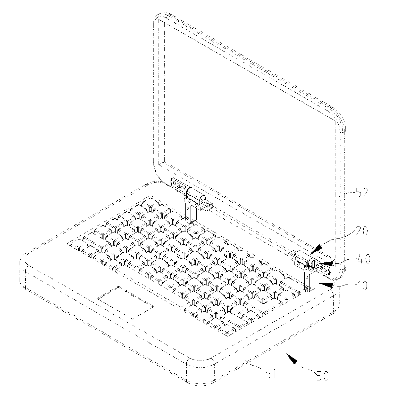
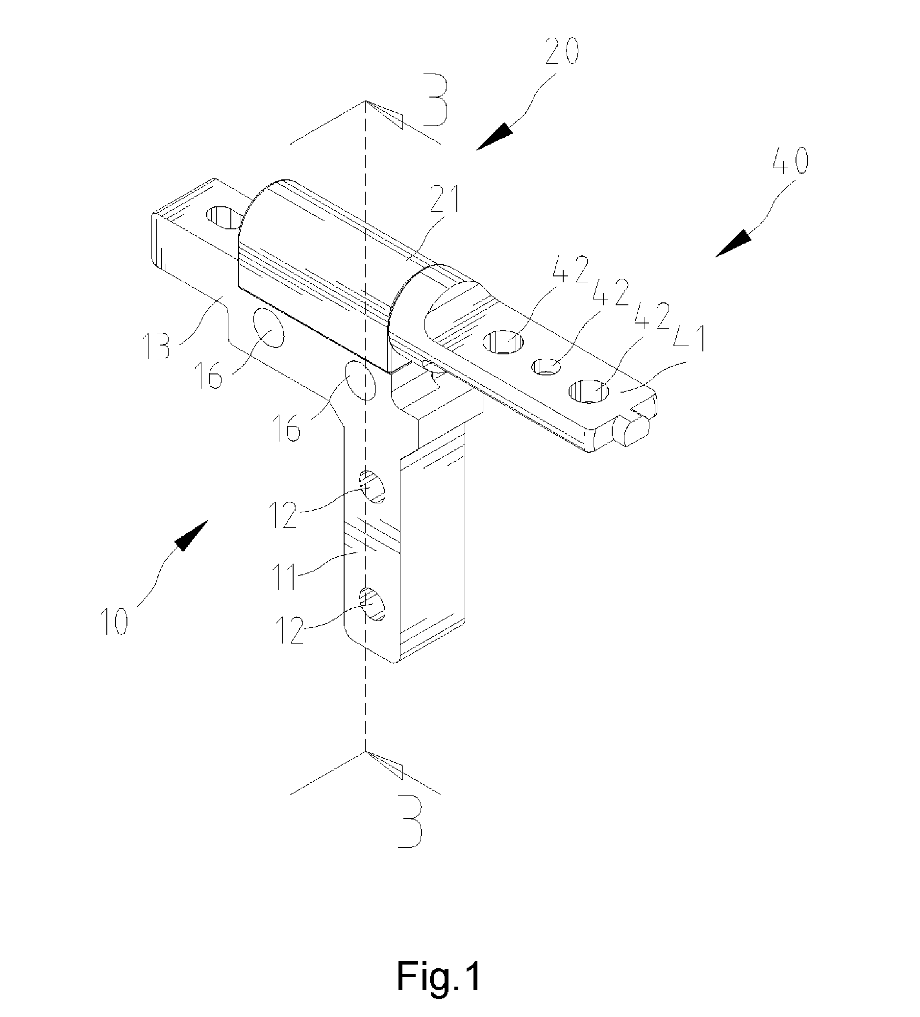
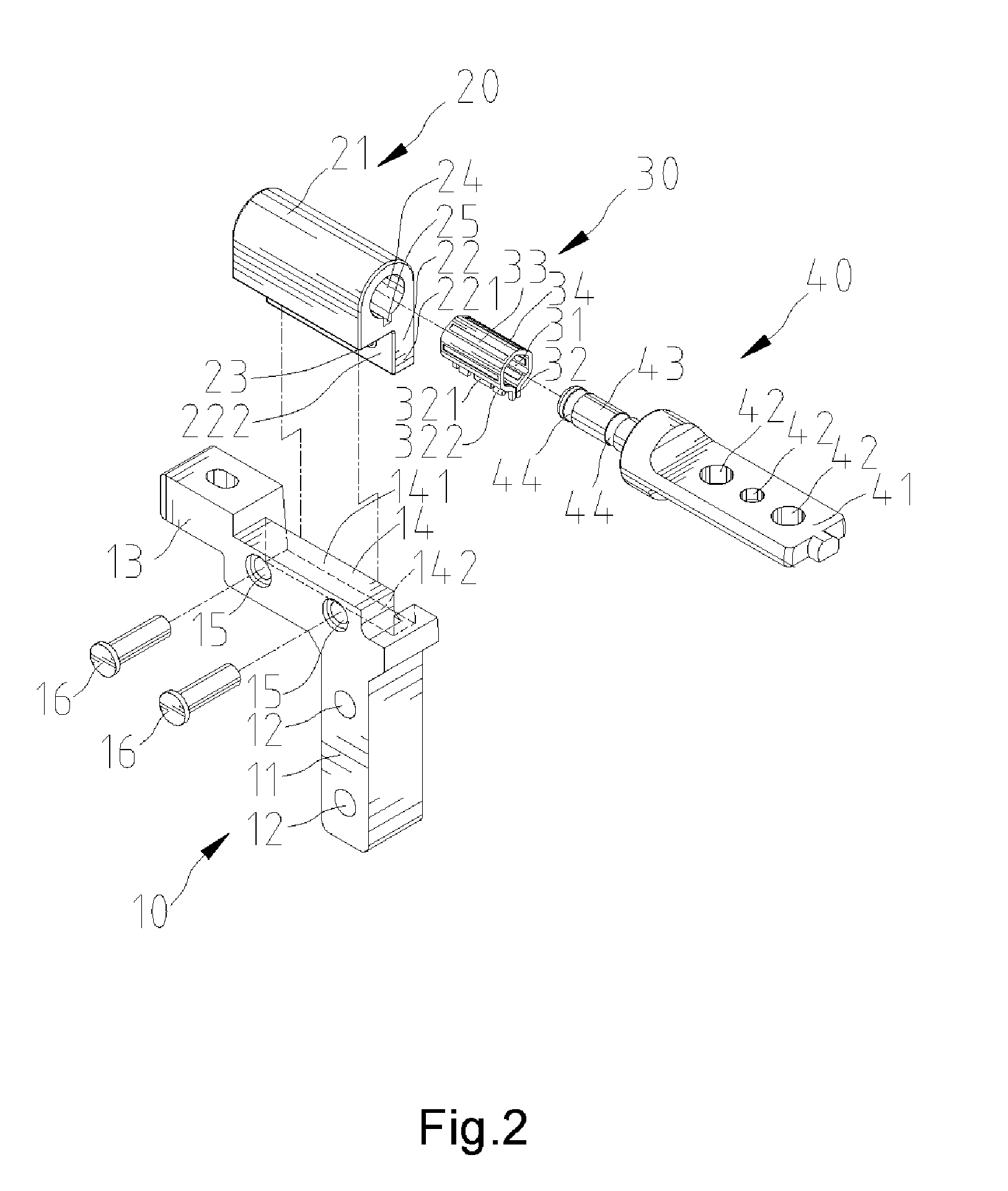
[0020]Referring to FIGS. 1 through 3, there is shown a hinge according to a first embodiment of the present invention. The hinge can be used in a laptop computer 50 including a host 51 and a liquid crystal display (“LCD”) 52 as shown in FIG. 4. The hinge includes a first connector 10, a casing 20, a bush 30 and a second connector 40.

[0021]The first connector 10 includes a post 11, a beam 13 transversely extended from the post 11 and a connective device 14 formed on the beam 13. The connective device 14 includes a wall 141 and a cutout 142 next to the wall 141. Two apertures 15 are defined in the wall 141.

[0022]The casing 20 includes a tube 21 and a connective device 22 extended from the tube 21. The tube 21 defines a space 24 along the axis and a groove 25 in communication with the space 24. The connective device 22 includes a wall 221 and a cutout 222 near the wall. Two apertures 23 are defined in the wall 221.

[0023]The bush 30 includes a sleeve 31 and a positioning device 32 forme...


PUM


Abstract

A hinge includes a first connector, a casing, a bush and a second connector. The first connector includes a post and a beam extended from the post. The post can be connected to a portion of a laptop computer. The casing is non-rotationally mounted on the beam. The bush is disposed non-rotationally in the casing. The second connector includes a shaft and a plate extended from the shaft. The shaft is rotationally inserted in the bush. The plate can be connected to another portion of the laptop computer.

Description

BACKGROUND OF INVENTION[0001]1. Field of Invention[0002]The present invention relates to a hinge and, more particularly, to a hinge for use in a laptop computer.[0003]2. Related Prior Art[0004]Referring to FIG. 8, a conventional hinge includes a first connector 1, a lining 2, a bush 3 and a second connector 4. The first connector 1 includes a post and a socket extended from the post. The post of the first connector 1 is connected to a host of a laptop computer. The lining 2 is fit in the socket of the first connector 1. The bush 3 is an arched elastic strip. The bush 3 is fit in the lining 2. The second connector 4 includes a plate and a shaft extended from the plate. The shaft of the second connector 4 is inserted in the lining 2. The plate of the second connector 4 is connected to a liquid crystal display (“LCD”) of the laptop computer. The bush 3 damps the rotation of the shaft of the second connector 4 as the LCD is pivoted towards the host. It however requires high precision in...

Claims


Application Information

Patent Timeline
IPC IPC(8): G06F1/16E05C17/64
CPCE05D5/14E05D11/02E05D11/082E05Y2201/21E05Y2201/254Y10T16/54038E05Y2900/606G06F1/1616G06F1/1681E05D5/16E05Y2201/266
Inventor CHERN, JR-JIUN
Owner CHERN JR JIUN
Why Eureka
Try Eureka