
Dental attachment assembly and method

a technology of dental attachment and assembly method, which is applied in the field of dental attachment or anchoring structure, can solve the problems of wear and roll-out of the ring, and work best when perfectly straigh

Active Publication Date: 2008-06-26
ZEST IP HLDG
View PDF27 Cites 47 Cited by
  • Summary
  • Abstract
  • Description
  • Claims
  • Application Information

AI Technical Summary

Benefits of technology

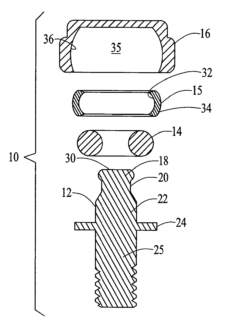
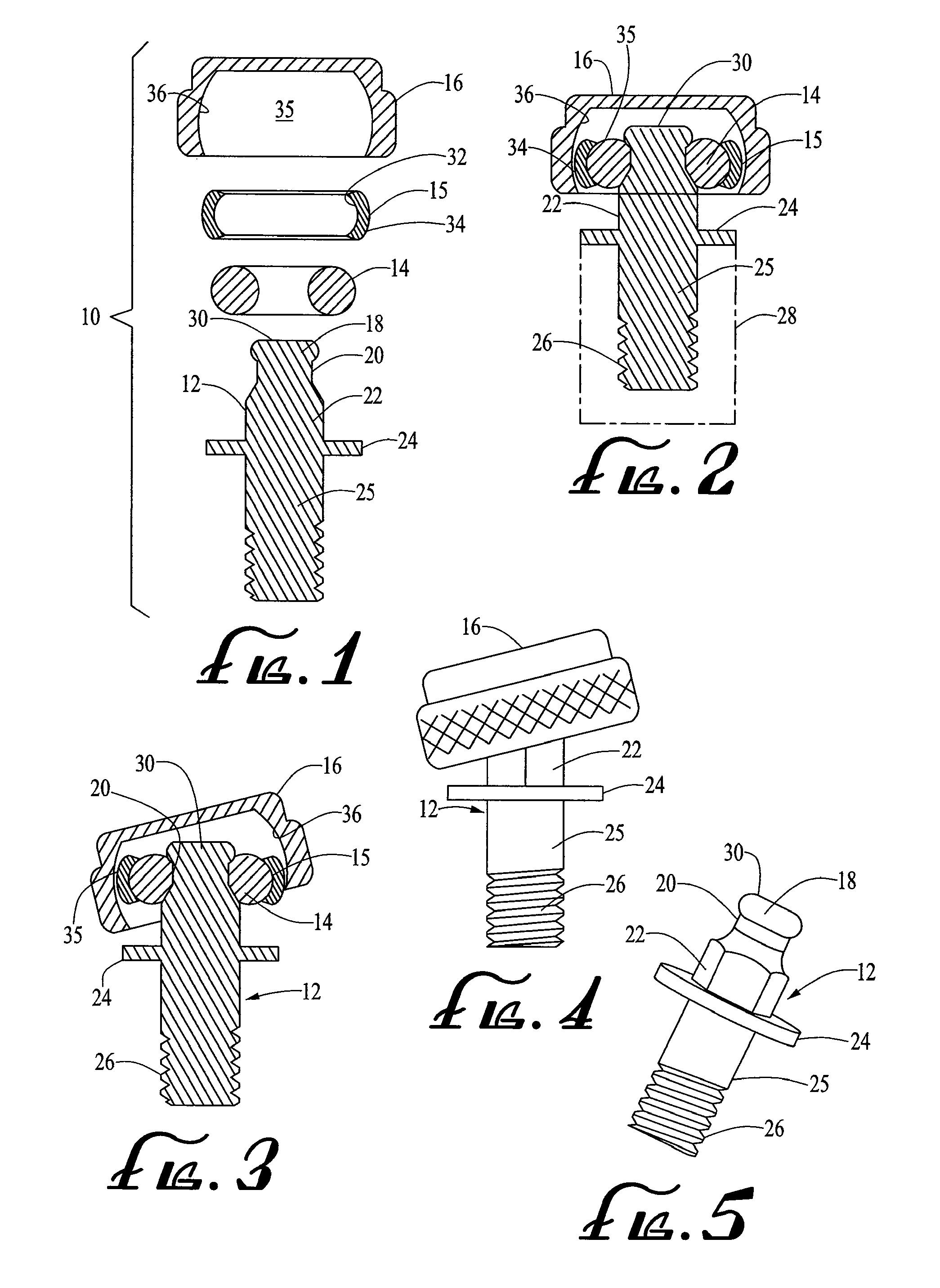
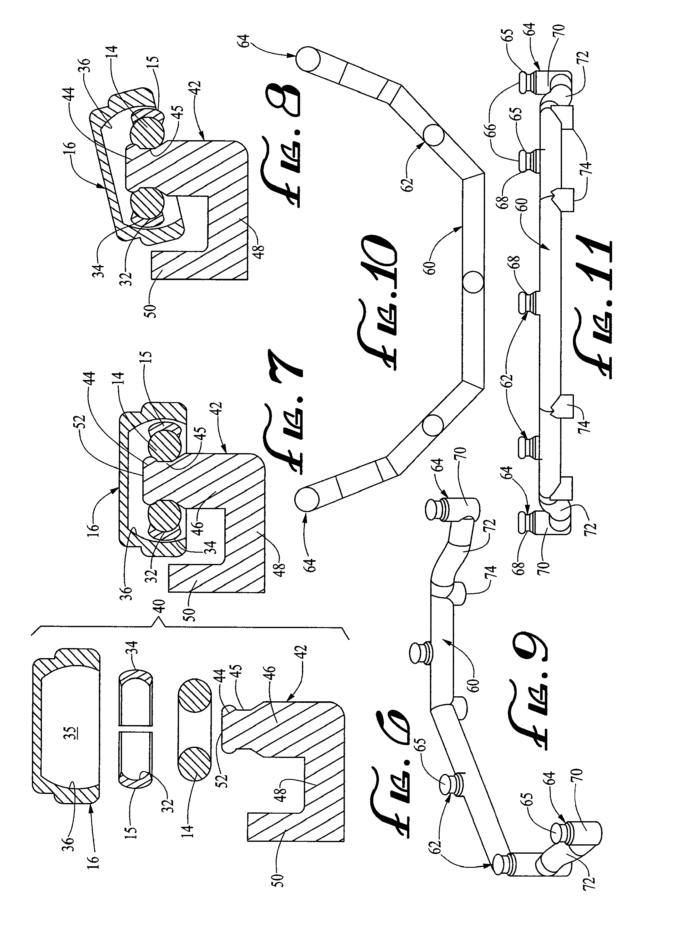
[0007]This arrangement provides vertical resilience due to the elastomeric ring as well as a pivoting action which can compensate for divergent implants. The abutment member may have a tail end portion configured for engagement in a mating bore in a non-vital root or an implant bonded into a root, or may have a distal extension for securing to an adjacent tooth, crown, or the end of a bar. In another embodiment, one or more abutment members are cast onto an elongate bar secured to two or more implants. The cap, retainer ring, and elastomeric ring may be adapted for use separately with an existing abutment for any O-ring attachment, allowing such existing abutments to be retrofitted with a pivoting or swiveling cap attachment.
[0008]In one embodiment, the abutment member may be a mini or small diameter implant with a threaded shaft or tail portion which is adapted to be implanted directly into a prepared bore in a patient's jaw bone. A series of such small abutment members may be splinted together by means of a bar of relatively small cross-sectional dimensions for added stability.

Problems solved by technology

One problem with O-ring or similar resilient ring attachments is that they work best when perfectly straight.
Any angulation of the abutment will cause wear and roll-out of the ring due to uneven biting forces.

Method used


Image

  • Dental attachment assembly and method
  • Dental attachment assembly and method
  • Dental attachment assembly and method

Examples


Embodiment Construction

[0039]Certain embodiments as disclosed herein provide for systems and methods for removably attaching a dental appliance such as a full denture, overdenture, partial denture, or the like in the mouth of a patient. For example, one method as disclosed herein allows for a cap to be cemented to the appliance with a resilient ring and outer, ring-shaped retainer pivotally mounted in the cap and adapted for snap engagement over the head of an abutment secured at an appropriate location in a patient's mouth.

[0040]After reading this description it will become apparent to one skilled in the art how to implement the invention in various alternative embodiments and alternative applications. However, although various embodiments of the present invention will be described herein, it is understood that these embodiments are presented by way of example only, and not limitation. As such, this detailed description of various alternative embodiments should not be construed to limit the scope or brea...


PUM


Abstract

A dental attachment system has an abutment member configured for attachment to a tooth root, implant, or adjacent tooth, the abutment member having a head and an annular seat adjacent the head. An elastomeric ring is configured for releasable engagement in the seat on the abutment member, and is retained in a retainer ring which in turn is in swivel engagement with a concave inner surface of a cavity in a cap which is secured in a recess in a dental appliance such as a denture, partial denture, or the like.

Description

BACKGROUND[0001]1. Field of the Invention[0002]The present invention generally relates to a dental attachment or anchoring structure for attaching a removable dental appliance such as a full denture, overdenture, partial denture, or the like to a remaining non-vital root, an adjacent tooth, or to an endosseous implant.[0003]2. Related Art[0004]There are many different types of dental attachments for releasably anchoring a dental appliance to one or more roots or implants, or to an adjacent tooth. In many cases, the attachments comprise mating, snap engageable male and female parts, one of which is attached to the denture and the other of which is attached to a root, implant, or adjacent tooth. One known attachment has a first part which is pivotally engaged in a cap secured in an implant, and a second part secured to an implant, root, or the like. Some attachments of this general type are described in U.S. Pat. Nos. 5,417,570, 6,030,219, and 6,299,447, for example.[0005]Another know...

Claims


Application Information

Patent Timeline
IPC IPC(8): A61C8/00
CPCA61C8/0018A61C8/0048A61C8/0053A61C13/2656A61C8/0087A61C8/0089A61C8/0057A61C8/0095
Inventor MULLALY, SCOTTZUEST, PAUL
Owner ZEST IP HLDG
Learn More