
Connector

a technology of connecting rods and connectors, applied in the direction of connecting rods, electrical appliances, coupling devices, etc., can solve the problem of not being able to ensure sufficien

Active Publication Date: 2008-06-26
YAZAKI CORP
View PDF12 Cites 15 Cited by
  • Summary
  • Abstract
  • Description
  • Claims
  • Application Information

AI Technical Summary

Benefits of technology

[0012]Hence, an object of the present invention is to provide a connector which allows firm engagement of a connector housing with a housing cover.
[0017]With the construction described above, since the flexible lock arm has the first arm and the second arm which includes the first retaining projection, a rear end of the second arm can be flexibly deformed depending solely upon a deformation of a front end of the first arm, regardless of a difference of amounts of slanting of a front side and a rear side of the stay portion. Thus, more effective and reliable engagement of the connector housing with the housing cover can be achieved.
[0019]With the construction described above, since the connector housing has the fulcrum projection, and the housing cover has the supporting portion, the amount of deformation of the rear end of the second arm with respect to the amount of deformation of the front end of the first arm can be made larger. This is because the fulcrum projection on the front side viewed from the stay portion acts as a fulcrum when the front end of the flexible lock arm is flexibly deformed due to the retention reinforcement portion. Thus, more effective and reliable engagement of the connector housing with the housing cover can be achieved.
[0021]With the construction described above, since the retaining surfaces of the first retaining projection and the second retaining projection respectively are tapered, sloping in the engagement direction, the first retaining projection can be displaced more flexibly in the engagement direction. Thus, more effective and reliable engagement of the connector housing with the housing cover can be achieved.

Problems solved by technology

Also, since the connectors with reduced size and less height do not allow the front end of the arm 122 to be bent to a large extent, the conventional connectors fail to ensure sufficient engagement of the female connector housing 100 with the fitting detection member 200.

Method used


Image

  • Connector
  • Connector
  • Connector

Examples


Embodiment Construction

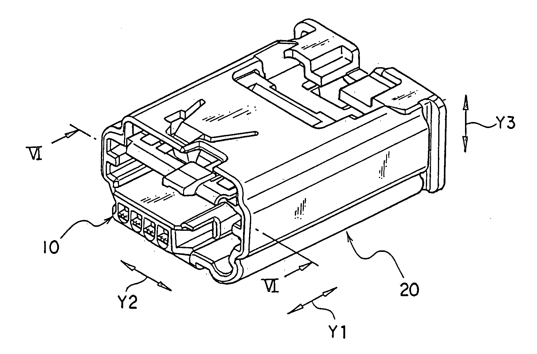
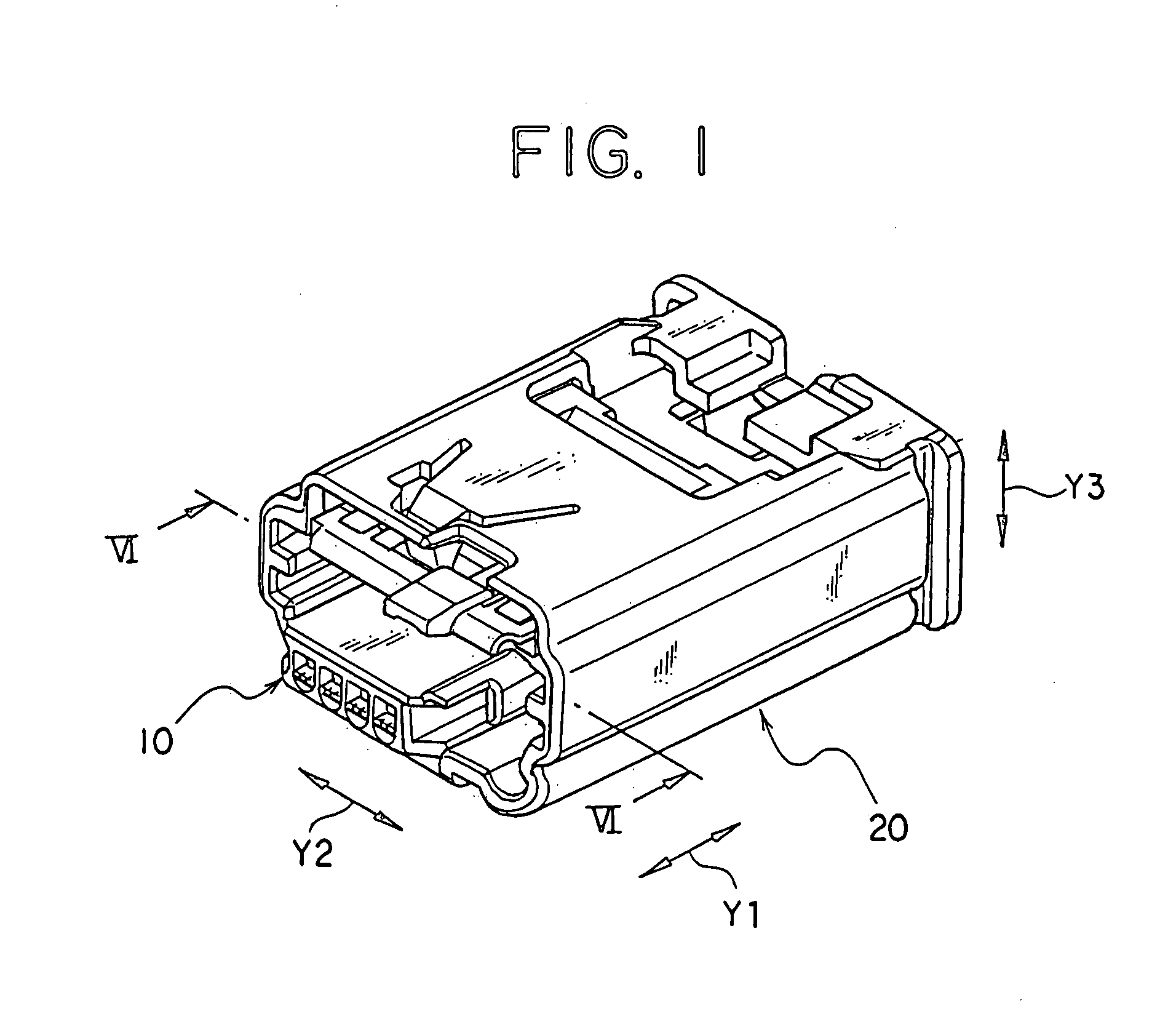
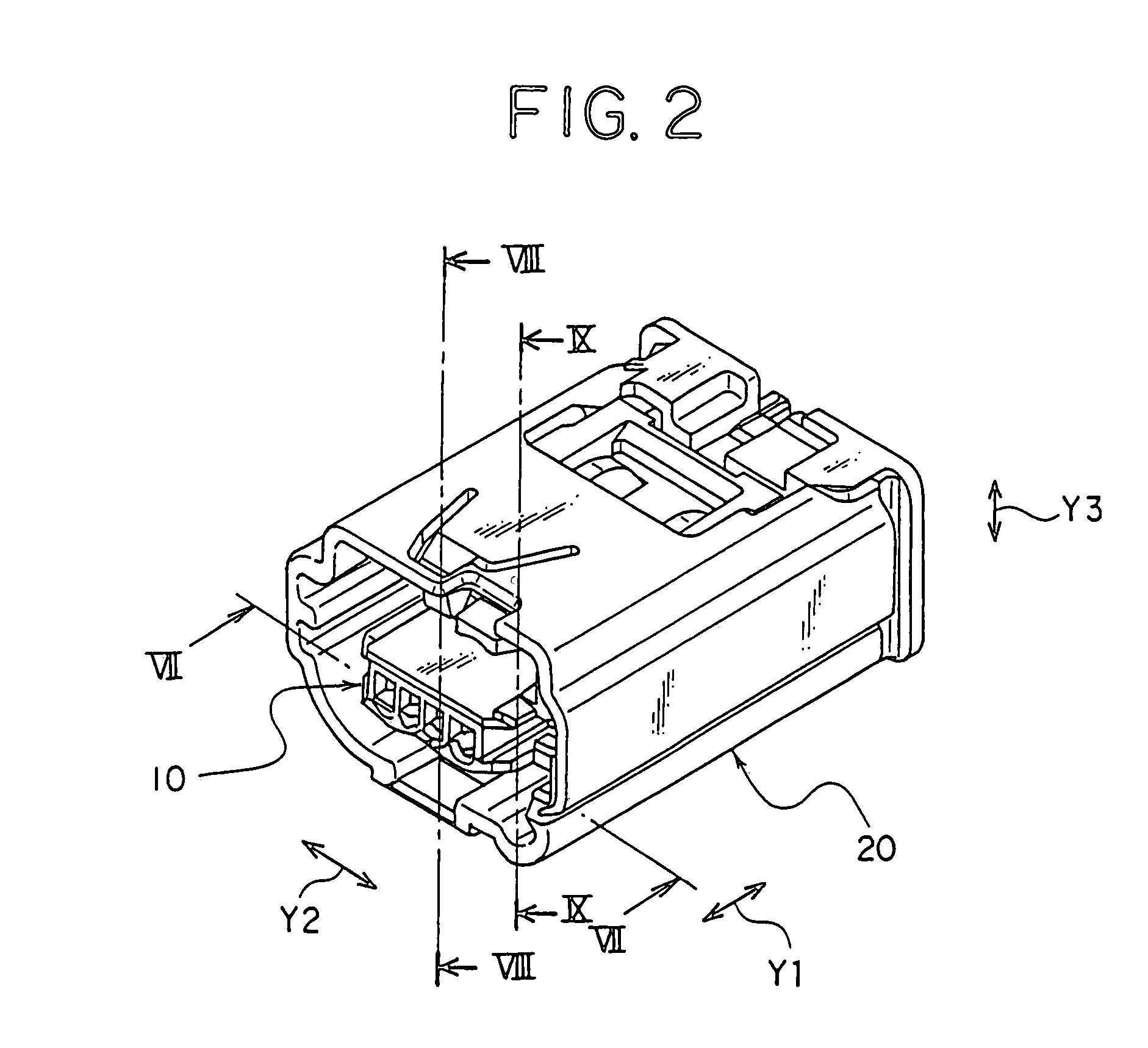
[0039]An embodiment of the connector of the present invention is described with reference to the attached drawings 1 to 14. Note that arrows Y1, Y2, and Y3 in the drawings indicate length, width, and thickness directions of the connector, respectively.

[0040]Let us start with taking a look at FIGS. 1 and 2 to overview a configuration of the connector of the present invention. The connector has a connector housing 10, which is a female connector housing, and a housing cover 20 which receives the connector housing 10 thereinside. The housing cover 20 of this embodiment is an outer cover with connector position assurance (CPA) functionality, and has a similar function as in a conventional fitting detection member. When the connector housing 10 is not in complete engagement with a mating male connector housing, the connector housing 10 cannot be slid from an initial position (see FIG. 1) to a complete engagement position (see FIG. 2). As shown in FIGS. 1 and 2, respectively, the initial ...


PUM


Abstract

A flexible lock arm has a first arm which extends from a stay portion to an inflection point of the first arm on a front side of a terminal along a length direction indicated by arrow Y1 and a second arm which extends from the inflection point of the first arm to a rear end viewed from a stay portion. A first retaining projection is provided on the second arm.

Description

CROSS REFERENCE TO RELATED APPLICATIONS[0001]This application is based on Japanese Patent Application No. 2006-345907, the contents of which are hereby incorporated by reference.BACKGROUND OF THE INVENTION[0002]1. Field of the Invention[0003]This invention relates to a connector and, in particular, to a connector which includes a connector housing with a housing body having a terminal receiving chamber receiving thereinside a terminal, and a housing cover receiving the connector housing.[0004]2. Description of the Related Art[0005]Patent Document 1 (Japanese Patent Application Laid-Open Publication No. 2004-220970) discloses a conventional half-fitting preventing connector (see FIG. 14). The half-fitting preventing connector includes a female connector housing 100 as a housing connector with the terminal receiving chamber that receives a female terminal TF and the housing cover, i.e., a fitting detection member 200 that receives the female connector housing 100.[0006]Unless the fema...

Claims


Application Information

Patent Timeline
Patent Type & Authority Applications(United States)
IPC IPC(8): H01R13/629
CPCH01R13/6272H01R13/506
Inventor SHIGETA, YOSHINORITSURUTA, AKIHIROKAZAMA, TAKESHIKUBOTA, HIROMASA
Owner YAZAKI CORP
Learn More