Recoil shock device in toy gun

Active Publication Date: 2008-07-03
TOKYO MARUI
View PDF10 Cites 32 Cited by
  • Summary
  • Abstract
  • Description
  • Claims
  • Application Information

AI Technical Summary

Benefits of technology

[0006]The present invention has been made taking the above points into consideration. It is therefore an object of the present invention to provide a recoil shock device capable of obtaining the same recoil shock as that in a case where the weight of a piston is increased, without increasing the weight of the piston by separately providing a movable part and a weight in a piston / cylinder unit. It is another object of the present invention to provide a recoil shock device which allows a shooter to feel a recoil shock as in a real gun, without damaging the outer appearance of a gun.
[0012]An elastic body which is compressed by retreat movement of the communicating part can be interposed between the communicating part and the weight and / or between the piston and the communicating part. According to the above description, since a force generated in the piston / cylinder unit is transmitted to the movable part, the communicating part, and the weight, the transmission action can be changed to an indirect action, not a direct action by interposing the elastic body between the communicating part and the weight. Further, a gap, though slight, also occurs in transmission time. Moreover, the elastic body functions to absorb a shock accompanying the transmission of force among the piston, the communicating part and the weight to prevent damage thereto.
[0013]In addition, a recoil shock starts in a state where a force exerted by the piston / cylinder is transmitted to the weight to bring the recoil spring into a compressed state and the recoil shock becomes remarkable as the weight advances along with the recoil spring which is extended by its resilient force. Thus, in the present invention, the weight retreats with compression of the recoil spring, and thereafter advance of the weight is made synchronized with the advance of the movable part at the time of the advance thereof, so that a shooter can feel a recoil shock like a real gun, even in slight movement of the weight. When a stronger recoil spring is used, it deviates toward faster side, whereas when a weaker recoil spring is used, it deviates toward slower side.
[0014]Since the present invention is configured and operates as described above, the weight is driven by the recoil spring by separately forming the movable part and the weight of the piston / cylinder. Thus, the present invention exhibits remarkable effects that the same recoil shock as that in a case where the weight of the piston is increased can be obtained even without increasing the weight of the piston, and the outer appearance of the toy gun also is not damaged.

Problems solved by technology

However, if the piston drives the weight due to operation of the cylinder even in a case where any bullet is not fired, it is needless to say that imitated recoil cannot be obtained.

Method used


Image

  • Recoil shock device in toy gun
  • Recoil shock device in toy gun
  • Recoil shock device in toy gun

Examples


Embodiment Construction

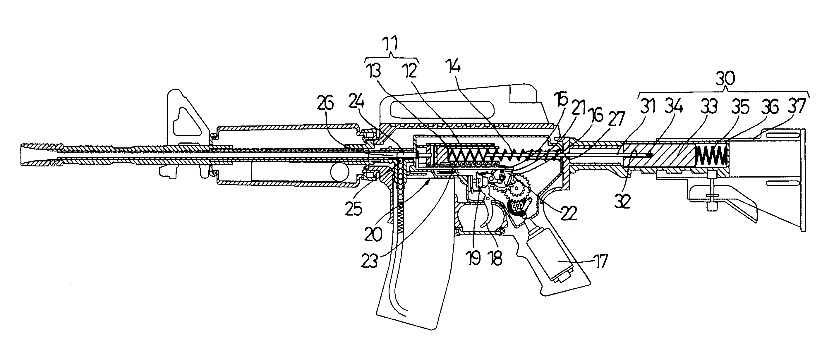
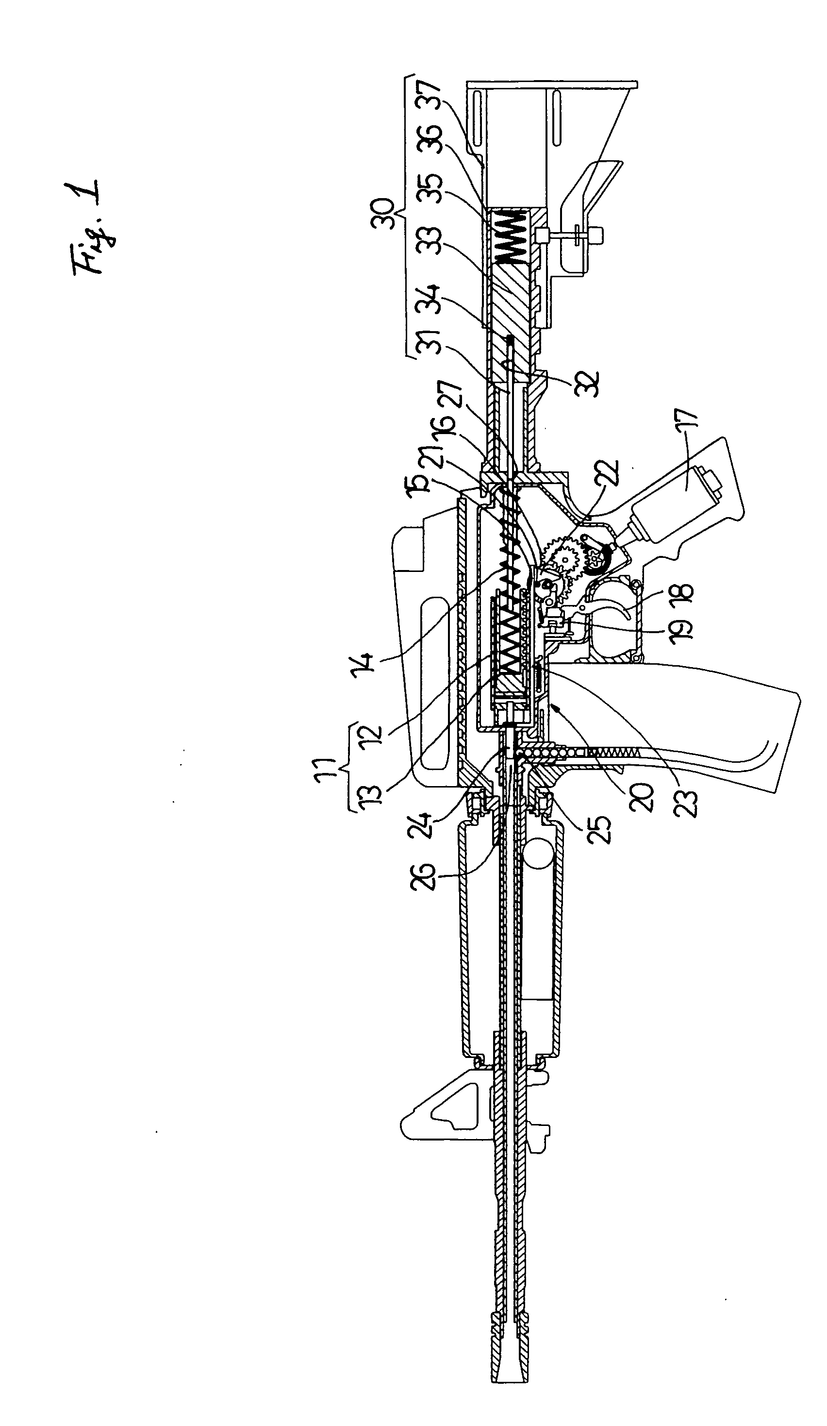
of a toy gun to which a recoil shock device according to the present invention is applied;

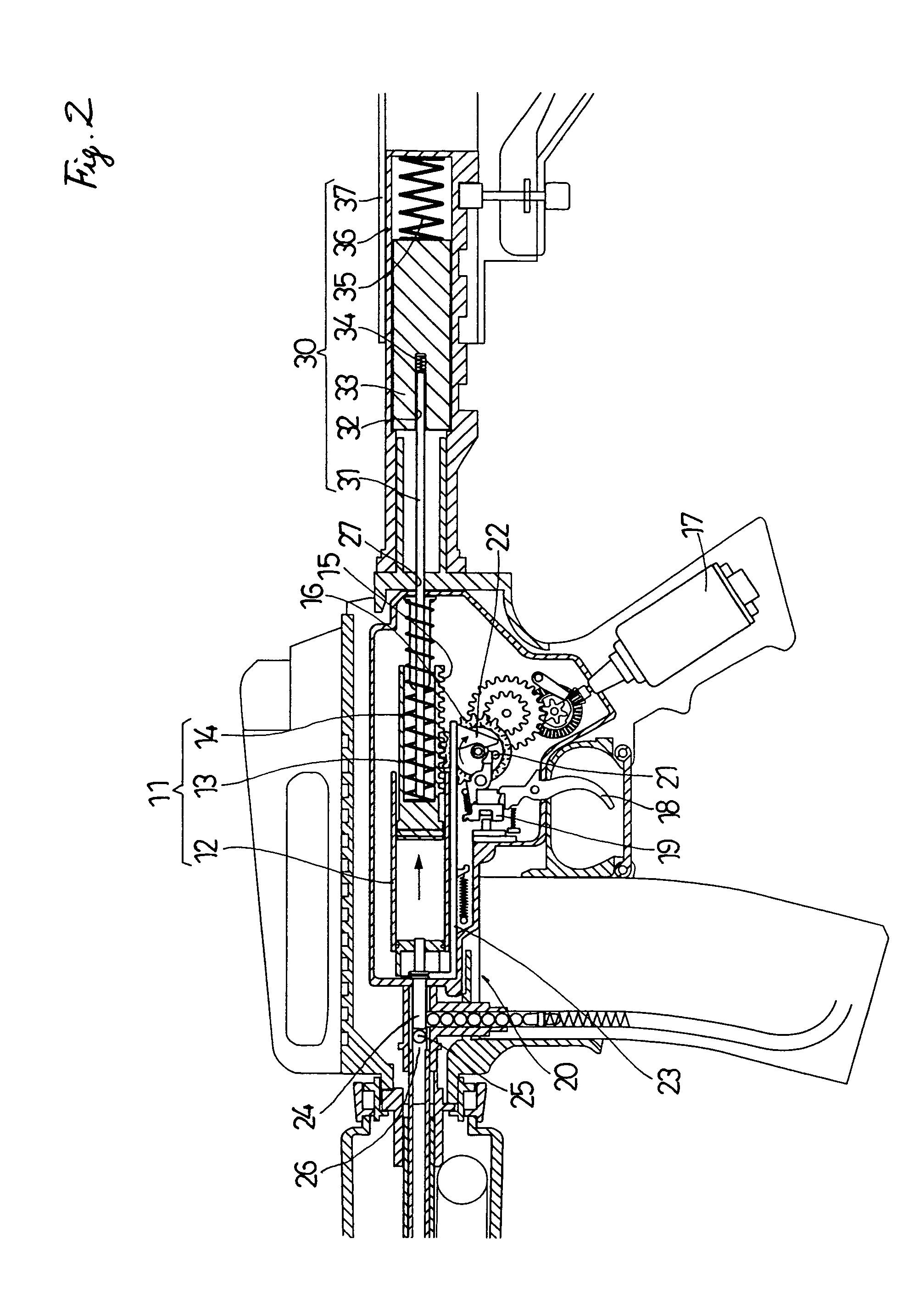
[0017]FIG. 2 is a longitudinal sectional view of Example 1 of the device shown in FIG. 1;

[0018]FIG. 3 is a longitudinal sectional view showing that a recoil spring of the device is compressed;

[0019]FIG. 4 is a longitudinal sectional view showing that the recoil spring generates a recoil shock;

[0020]FIG. 5 is a longitudinal sectional view showing Example 2 of the toy gun to which a recoil shock device according to the present invention is applied;

[0021]FIG. 6 is a longitudinal sectional view showing that a recoil spring of the device is compressed;

[0022]FIG. 7 is a longitudinal sectional view showing Example 3 of the toy gun to which a recoil shock device according to the present invention is applied; and

[0023]FIG. 8 is a longitudinal sectional view showing that a recoil spring of the device is compressed.

DESCRIPTION OF THE PREFERRED EMBODIMENTS

[0024]Hereinafter, the present invention will be de...


PUM


Abstract

There is provided a recoil shock device capable of obtaining the same recoil shock as that in a case where the weight of a piston is increased, without increasing the weight of the piston by separately providing a movable part and a weight of a piston / cylinder. There is also provided a recoil shock device capable of obtaining a recoil shock similar to that in a real gun, without damaging the outer appearance of a gun. In order to drive a weight to obtain imitated recoil, i.e., a recoil shock by operation of a movable part in a piston / cylinder which generates compressed air, a communicating part 31 which is moved in its retreating direction by the movable part 13 is provided, and a recoil spring 35 which receives a force transmitted to the weight 33 via the communicating part 31 by the movable part 13 so as to be in a compressed state is provided. A reaction that accompanies movement of the weight 33 when the recoil spring 35 is compressed and the recoil spring 35 is then extended by its resilient force is transmitted to a main body 37 of the gun.

Description

BACKGROUND OF THE INVENTION[0001]1. Field of the Invention[0002]The present invention relates to a device capable of obtaining simulated recoil by driving a weight by operation of a movable part in a piston / cylinder unit which generates compressed air.[0003]2. Description of Related Art[0004]Similar to real guns which generate recoil at the time of firing of bullets; attempts to reproduce imitated recoil (recoil shock) in toy guns have conventionally been performed. As recoil imparting methods that appear in toy guns which are put on the market, there is a method capable of obtaining shock by making a weight heavy to obtain shock in a toy gun having a piston / cylinder which generates compressed air. Therefore, it is necessary to make the weight heavy in obtaining sufficient shock. If the weight is made heavy, a need for strengthening a piston spring arises in order to avoid a reduction in the speed of bullets. Strengthening the piston spring increases the load of cocking a piston pum...

Claims


Application Information

Patent Timeline
IPC IPC(8): F41C3/00
CPCF41B11/89F41B11/644
Inventor IWASAWA, TATSUO
Owner TOKYO MARUI
Why Eureka
Try Eureka