Steering apparatus
a technology of electric steering and upper bracket, which is applied in the direction of steering columns, steering components, steering columns, etc., can solve the problems of affecting the smooth tilt position adjustment, abnormal noise, and a lot of labor hours taken to mount the upper bracket of the vehicle body to the vehicle body, so as to achieve smooth tilt position adjustment and reduce weight
- Summary
- Abstract
- Description
- Claims
- Application Information
AI Technical Summary
Benefits of technology
Problems solved by technology
Method used
Image
Examples
embodiment 1
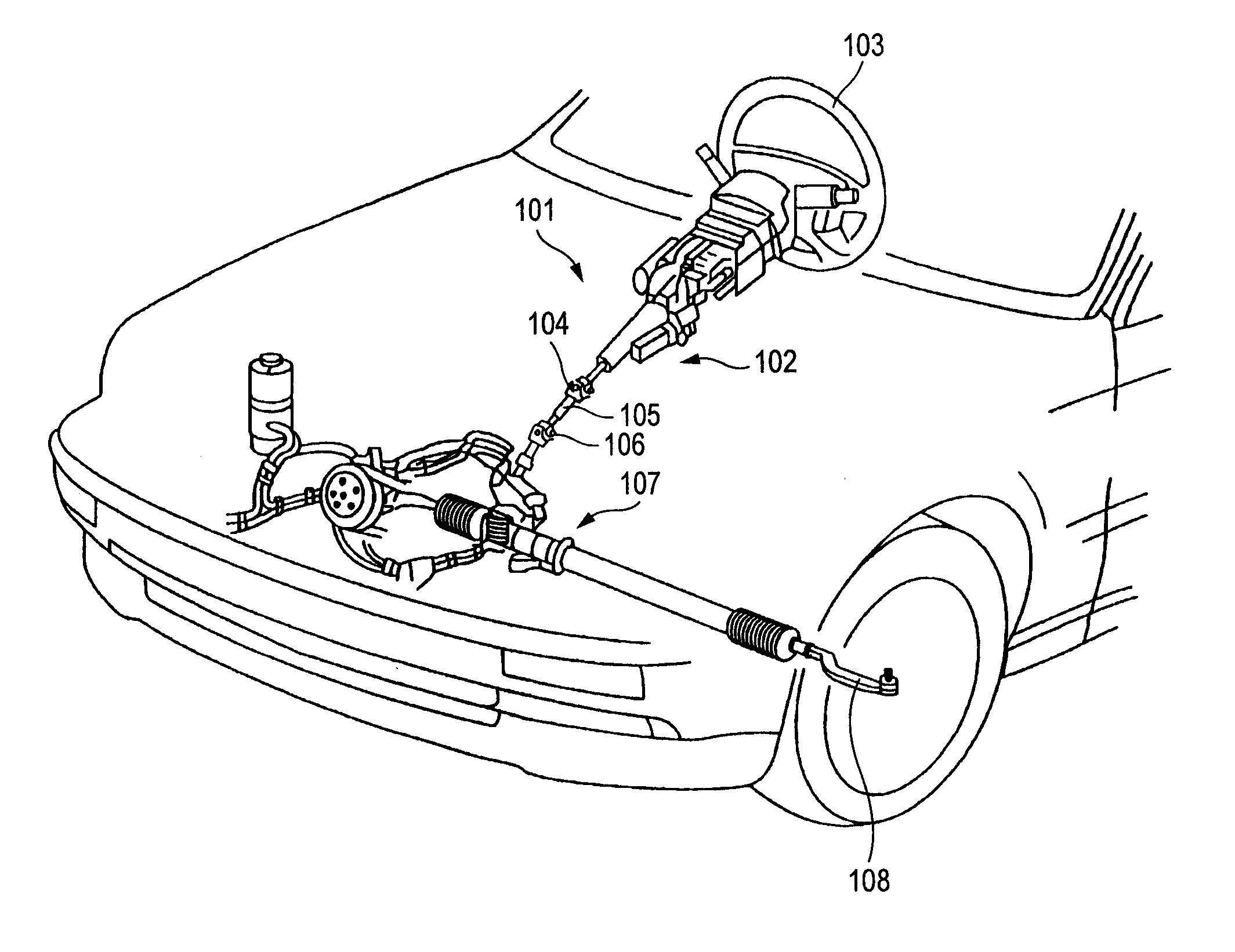
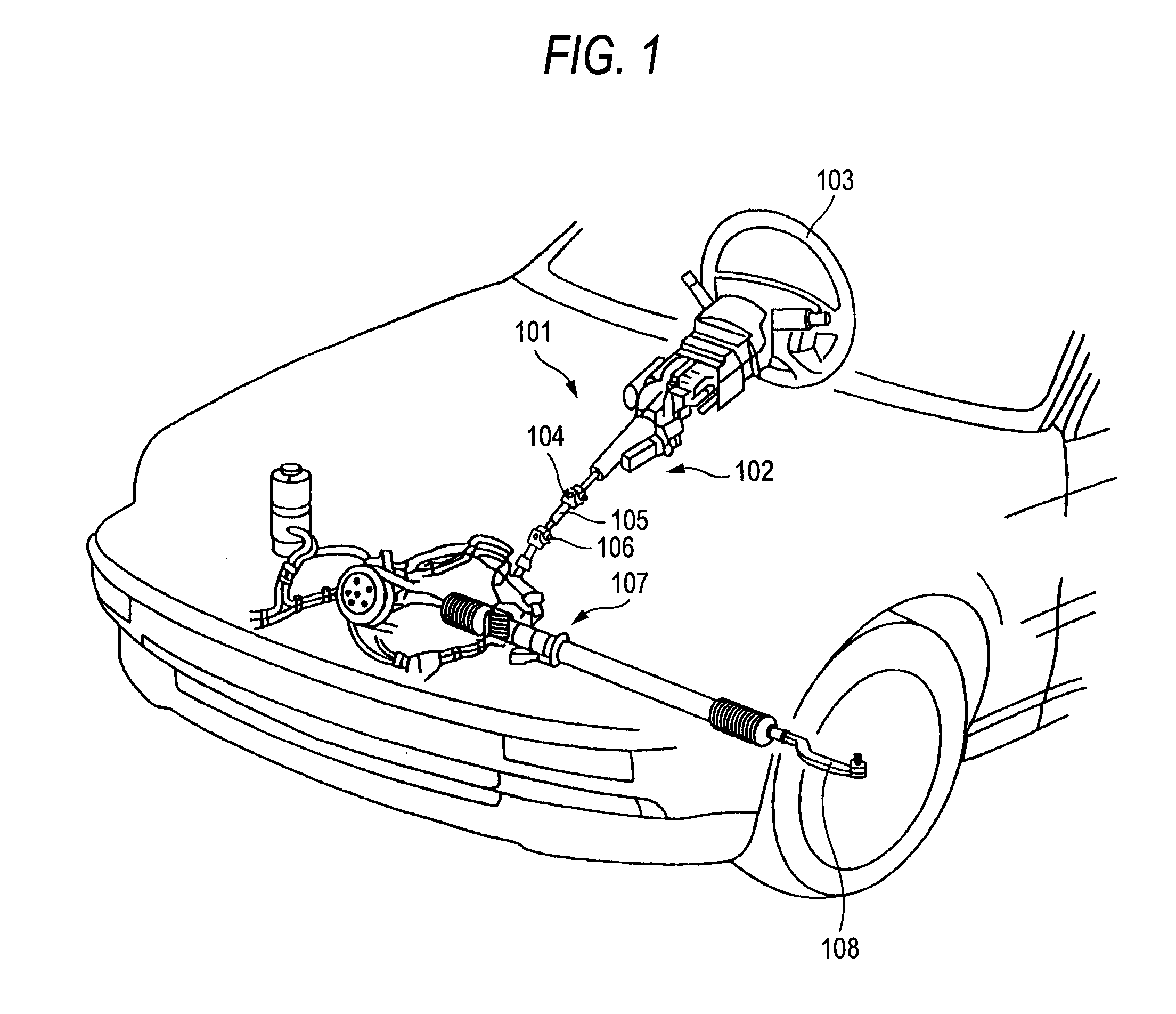
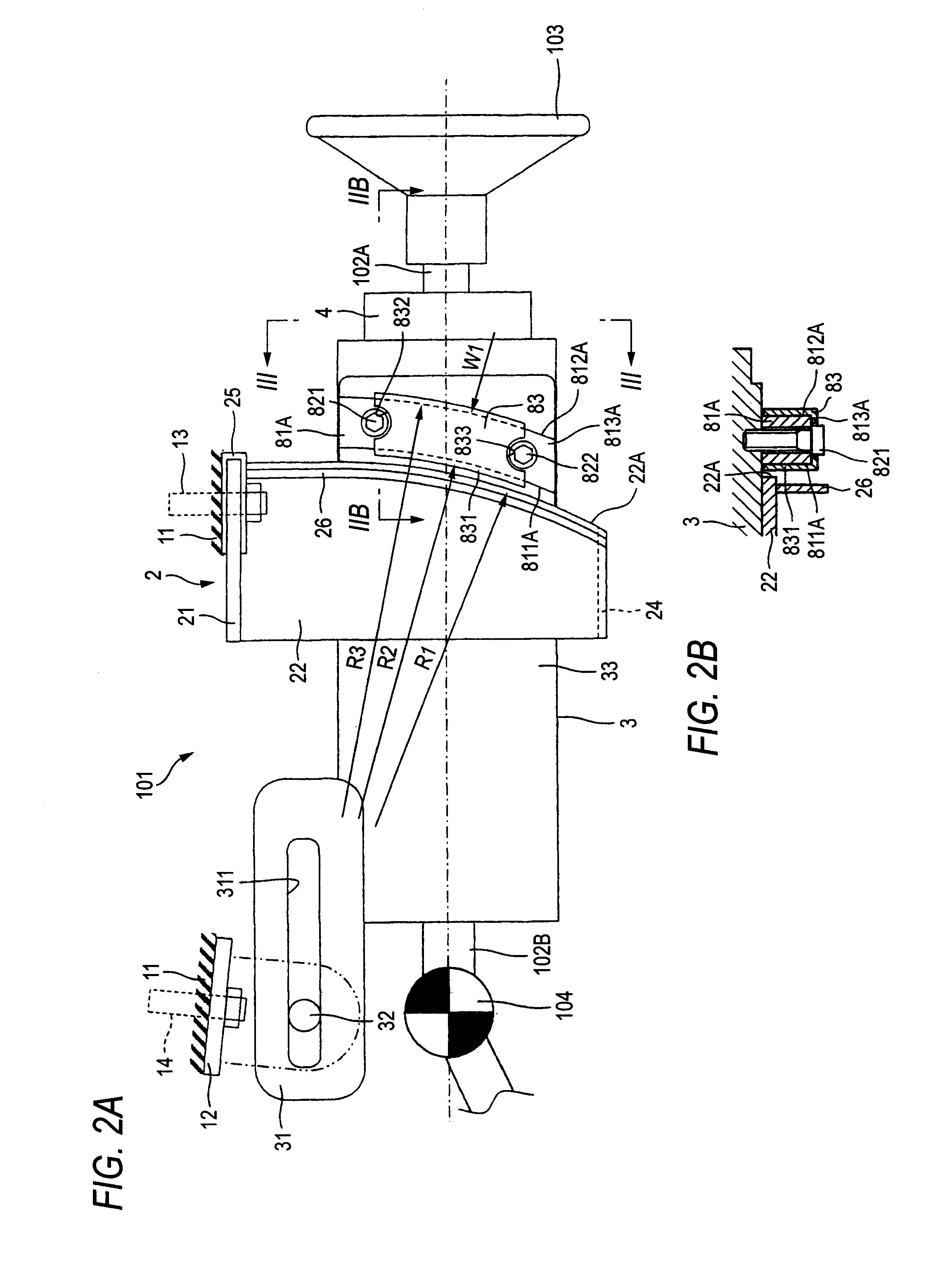
[0067]FIG. 1 is an overall perspective view showing a state in which an electric steering apparatus 101 of the invention is mounted on a vehicle. The electric steering apparatus 101 supports a steering shaft 102 rotatably. A steering wheel 3 is mounted on the steering shaft 102 at an upper end (a vehicular rear side) thereof, and an intermediate shaft 105 is connected to a lower end (a vehicular front side) of the steering shaft 102 via a universal joint 104.
[0068]A universal joint 106 is connected to a lower end of the intermediate shaft 105, and a steering gear 107, which is made up of a rack-and-pinion mechanism, is connected to the universal joint 106.
[0069]When the driver operates to turn the steering wheel 103, a rotational force exerted on the steering wheel 103 is transmitted to the steering gear 107 via the steering shaft 102, the universal joint 104, the intermediate shaft 105 and the universal joint 106, so as to move a tie rod 108 via the rack-and-pinion mechanism to the...
embodiment 2
[0114]Next, Embodiment 2 of the invention will be described. FIG. 7 is a side view showing a main part of an electric steering apparatus 101 of Embodiment 2 of the invention. In the following description, only constituent structural portions will be described which differ from those of Embodiment 1, and similar descriptions to those of Embodiment 1 will be omitted to avoid the repetition thereof. In addition, like reference numerals will be given to like components to those of Embodiment 1 for description.
[0115]In Embodiment 2, an example is illustrated in which a first guided surface of a first guided member is formed into a straight line shape which extends substantially in a tangential direction relative to a first guide surface 22A of a vehicle body mounting upper bracket 2. In the following description, the first guide surface 22A and a first guided member which are shown or visible in FIG. 7 will be described, and the description of a first guide surface 23A and a first guided...
embodiment 3
[0125]Next, Embodiment 3 of the invention will be described. FIG. 8 is a side view showing a main part of an electric steering apparatus 101 of Embodiment 3 of the invention. In the following description, only constituent structural portions will be described which differ from those of the embodiments that have been described above, and similar descriptions to those of the embodiments will be omitted to avoid the repetition thereof. In addition, like reference numerals will be given to like components to those of the embodiments for description.
[0126]In Embodiment 3, an example is illustrated in which a second guide surface, which is formed into an arc shape, is formed additionally on a vehicular front end face of a left-hand side plate 22 of a vehicle body mounting upper bracket 2, and a second guided member having a second guided surface which is adapted to slide along the second guide surface so formed when the tilt position of a lower column 3 is adjusted is additionally formed ...
PUM
 Abstract
Description
Claims
Application Information
 - R&D
- Intellectual Property
- Life Sciences
- Materials
- Tech Scout
- Unparalleled Data Quality
- Higher Quality Content
- 60% Fewer Hallucinations
Browse by: Latest US Patents, China's latest patents, Technical Efficacy Thesaurus, Application Domain, Technology Topic, Popular Technical Reports.
© 2025 PatSnap. All rights reserved.Legal|Privacy policy|Modern Slavery Act Transparency Statement|Sitemap|About US| Contact US: help@patsnap.com


