Pellet stove

a pellet stove and burner technology, applied in the field of pellet stoves, can solve the problems of reducing the ability to achieve complete and efficient combustion of fuel, requiring a considerable amount of effort to maintain and use, and reducing or at least substantially affecting the ability to allow the introduction of combustion air through the burning mass of fuel, so as to facilitate the cleaning of small amounts of ash

Inactive Publication Date: 2008-07-03
FAHRENHEIT TECH
View PDF17 Cites 12 Cited by
  • Summary
  • Abstract
  • Description
  • Claims
  • Application Information

AI Technical Summary

Benefits of technology

The invention describes a way to remove clinker from the bottom of a burnpot by sliding sidewalls of the burnpot across a stationary floor. This allows combustion air to be introduced upwardly into the burnpot and through the burning fuel from a cleanable airbox located underneath the burnpot. The advantage of removing clinker from the side rather than through the bottom of the burnpot is that clinker can be completely removed from the sidewalls of the burnpot by movement of the burnpot relative to stationary wedges that force clinker out of the burnpot and off of burnpot sidewalls. Additionally, because clinker is removed from the side rather than through the bottom of the burnpot, it is possible to easily clean any small amount of ash that falls through the openings in the stationary burnpot floor by operation of an airbox scraper, without requiring clinker disposal. Instead, operation of the airbox scraper allows any ash in the airbox to be dumped into a clinker pan.

Problems solved by technology

The technical problem addressed in this patent text relates to improving the efficiency and economics of heating residual buildings with biofuel-based furnaces or stoves, particularly those operated with minimal operator attention. Current designs often require significant maintenance efforts and struggle to efficiently utilize all the fuel provided. Additionally, current methods of removing clinker (the charcoal produced during combustion) result in incomplete combustion and produce unwanted waste.

Method used


Image

  • Pellet stove
  • Pellet stove
  • Pellet stove

Examples


Embodiment Construction

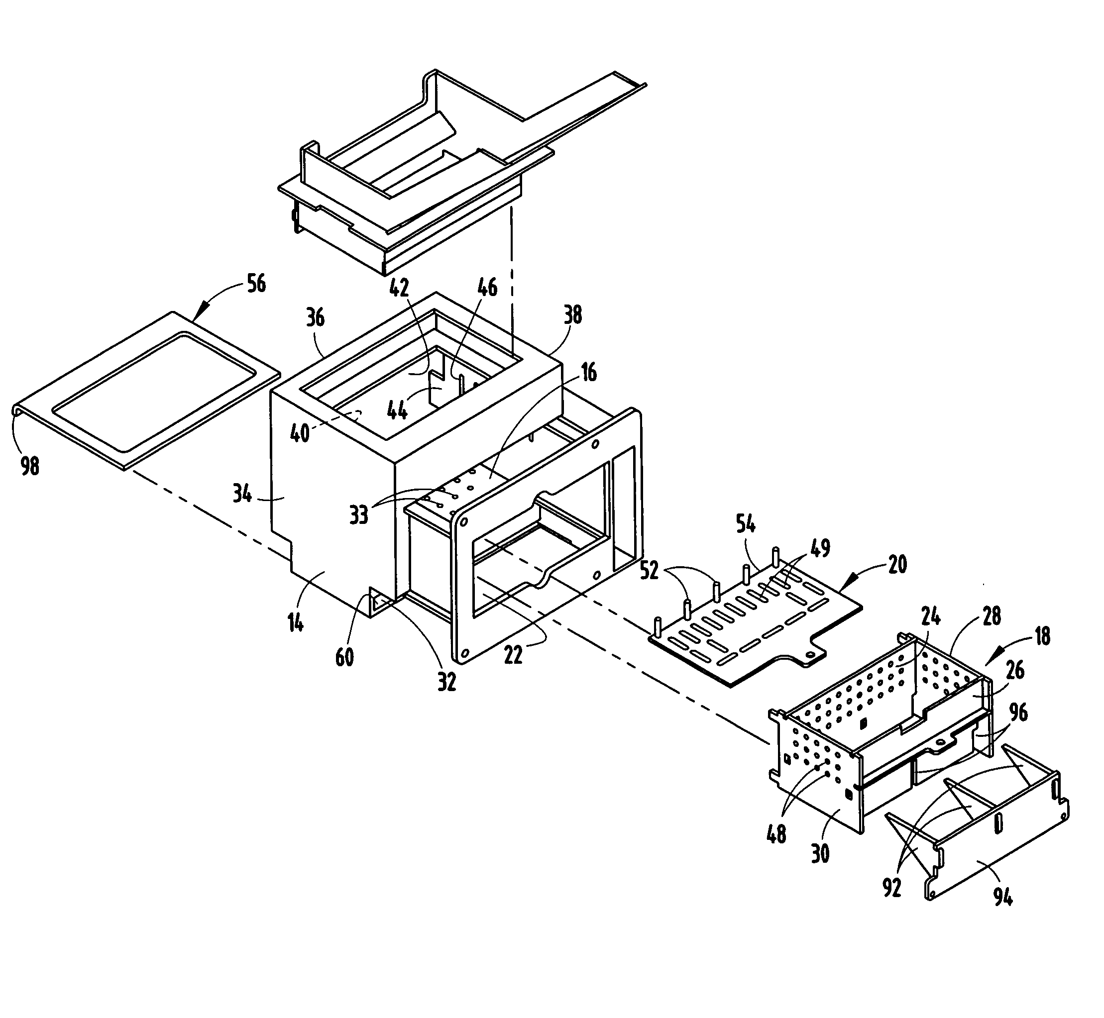
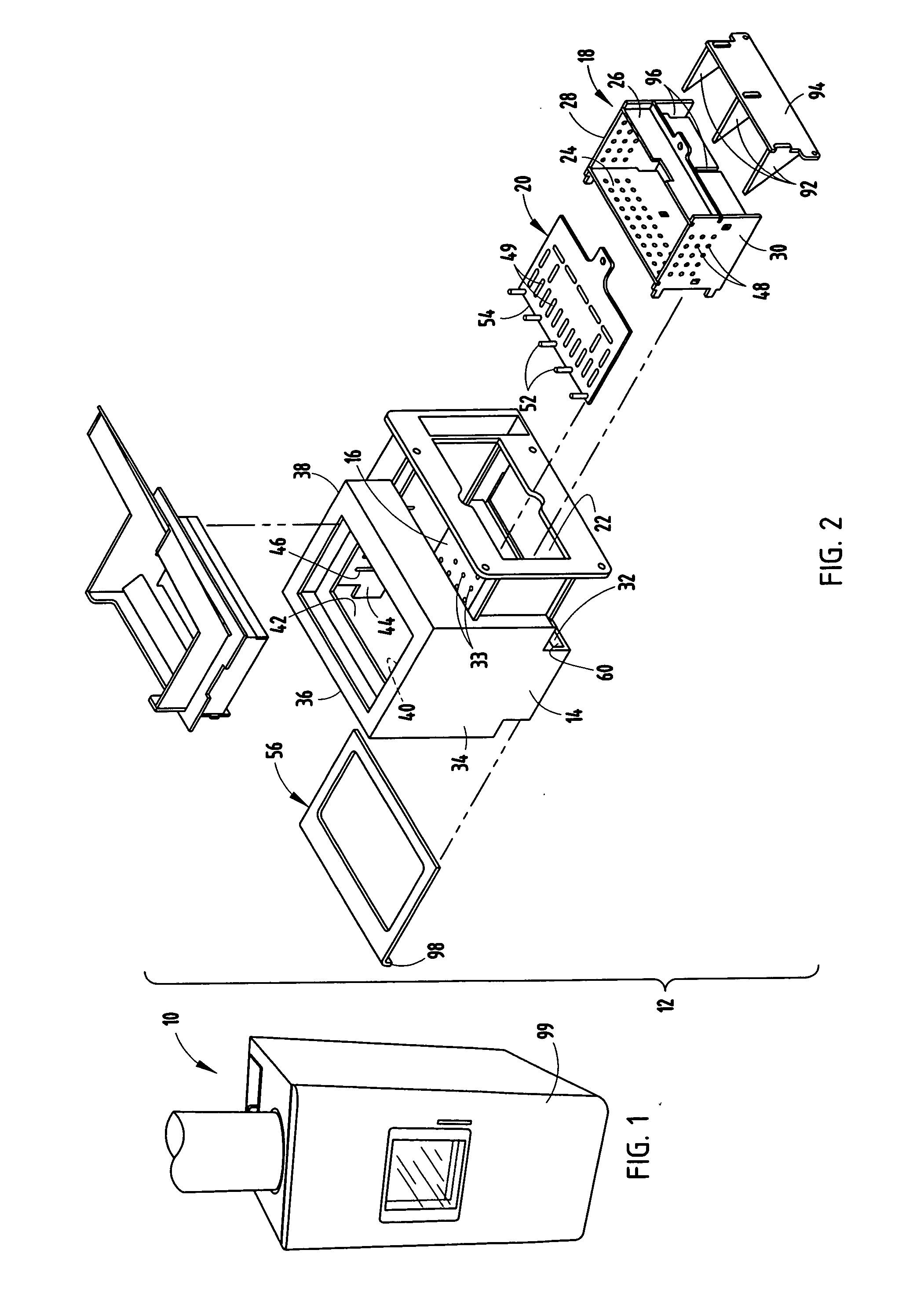
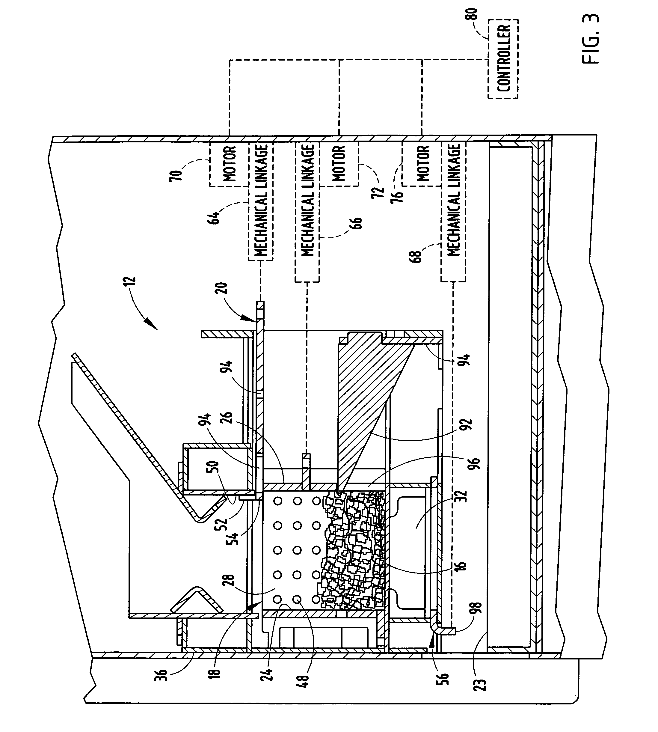
[0018]A pellet stove 10 (FIG. 1) in accordance with the invention includes a burnpot assembly 12 (FIG. 2) comprising a burnpot holder 14 having an immovable floor 16, a movable burnpot 18, and a combustible fuel retention plate 20. The burnpot 18 and burnpot holder 14 are configured to allow the burnpot to be moved from a normal fuel burning position to a clinker removal position in which the burnpot is located laterally adjacent the normal fuel burning position. Defined by burnpot holder 14, adjacent immovable burnpot floor 16, is an opening 22 that allows clinker and / or ash to drop through into clinker pan 23 located below opening 22.

[0019]While not constituting an essential part of the invention, pellet stove 10 will preferably include heat exchange means for extracting heat from the product gases of combustion and transferring the heat to air that is circulated in a building to heat living space within the building. Conventional furnace heat exchangers, fans, blowers and the lik...


PUM


Abstract

An improved burnpot assembly for a stove which allows clinker to be removed from the burnpot while simultaneously maintaining combustion includes a burnpot holder having an immovable floor, a burnpot movably supported on the burnpot holder, the burnpot including a front wall and an opposite back wall. The burnpot is movable with respect to the floor between a normal fuel burning position in which the walls of the burnpot and the immovable floor define a burnpot for combustion and a clinker removal position in which the burnpot is disposed laterally adjacent the immovable floor to allow clinker to drop from between the walls of the burnpot, such as into a clinker collection pan near the bottom of the stove.

Description


Claims


Application Information

Patent Timeline
Owner FAHRENHEIT TECH
Why Eureka
Try Eureka