Nozzle plate and method of manufacturing the same

Inactive Publication Date: 2006-08-10
SHARP KK
View PDF10 Cites 35 Cited by
  • Summary
  • Abstract
  • Description
  • Claims
  • Application Information

AI Technical Summary

Benefits of technology

[0177] This increases the margin for the etching by which the entered part of the liquid repellent film is removed. It is therefore possible to almost completely remove the entered part of the liquid repellent film, by sufficiently performing the etching.
[0178] As a result, since it is possible to prevent the l

Problems solved by technology

The arrangement above, however, has the following problems.
The warpage of the nozzle plate induces not only the decrease in precision of the joining between the nozzle plate and an inkjet head but also the decrease in the structural reliability of the nozz

Method used


Image

  • Nozzle plate and method of manufacturing the same
  • Nozzle plate and method of manufacturing the same
  • Nozzle plate and method of manufacturing the same

Examples


embodiment 1

[0200] Embodiment 1 of the present invention is described below with reference to the attached drawings.

[0201] (Nozzle Plate)

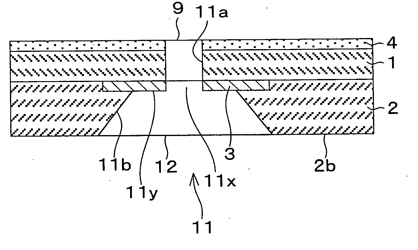
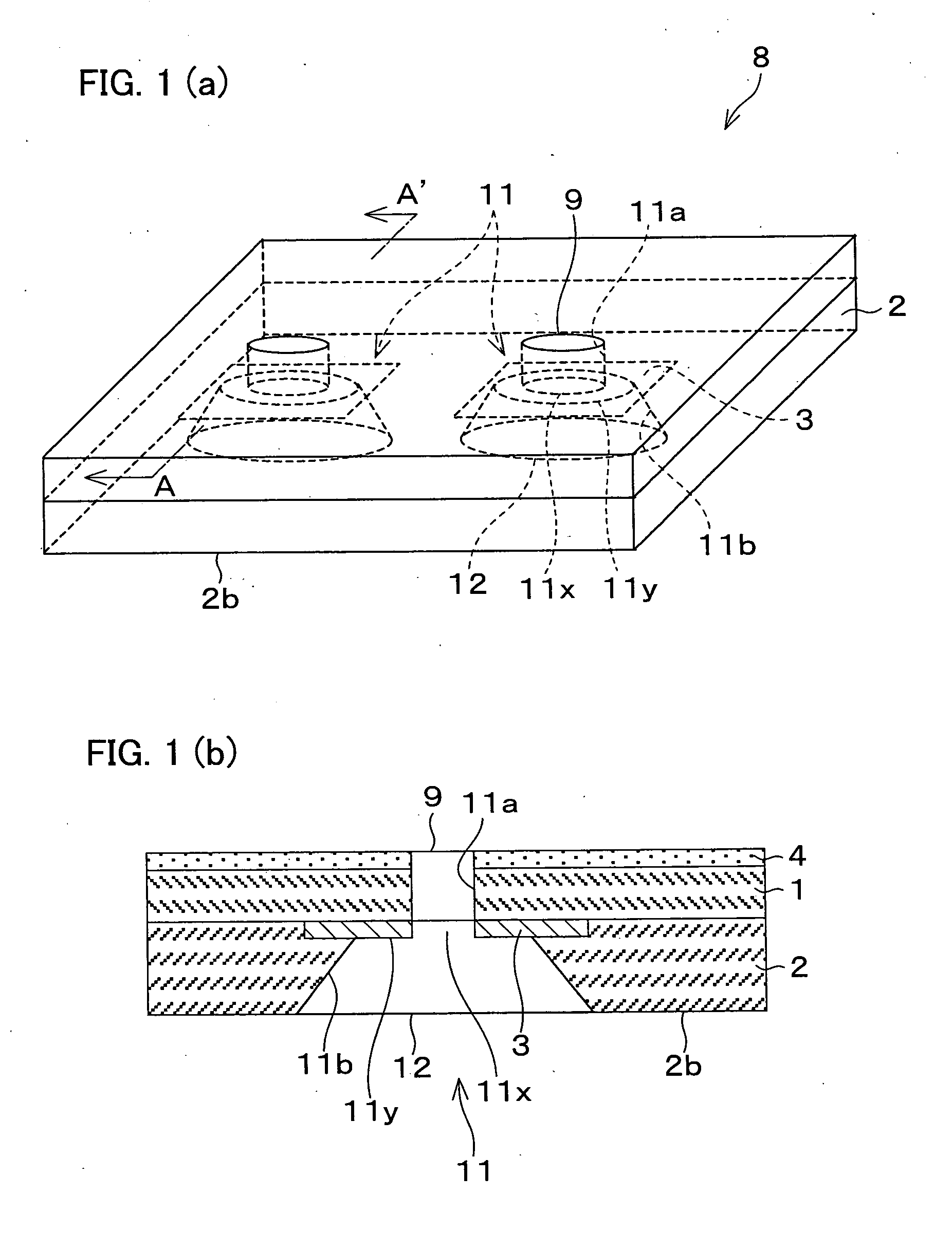
[0202]FIG. 1(a) is an oblique perspective view of a part of a nozzle plate of the present invention, which is used in a minute dot formation device. FIG. 1(b) is a cross section which is taken along a line A-A′ of FIG. 1(a). The nozzle plate has at least one liquid (liquid substance) discharge opening 9. In FIG. 1(a), there are two liquid discharge openings 9.

[0203] As shown in FIGS. 1(a) and 1(b), the nozzle plate 8 includes a first nozzle layer 1, a second nozzle layer 2, a stopper layer 3 (blocking layer), a liquid repellent film 4, and a nozzle hole 11. On the liquid discharging side of the first nozzle layer 1, the liquid repellent film 4 is formed. On the other side, the second nozzle layer 2 is formed. In the second nozzle layer 2, the stopper layer 3 is provided between the first and second nozzle layers 1 and 2, and is in touch with the first nozzl...

embodiment 2

[0262] The following will describe Embodiment 2 of the present invention in reference to figures.

[0263] (Nozzle Plate)

[0264]FIG. 5(a) is an oblique perspective view of a part of a nozzle plate of the present invention, which is used in a minute dot formation device. FIG. 5(b) is a cross section which is taken along a B-B′ line of FIG. 5(a). The nozzle plate has one or more liquid (liquid substance) discharge opening 90. In FIG. 5(b), there are two liquid discharge openings 90.

[0265] As shown in FIG. 5(a), the nozzle plate 80 includes a nozzle layer 10, a stopper layer 30 (blocking layer), a reinforcing plate 20, and a nozzle hole 110. On the liquid discharging side of the nozzle layer 10, a liquid repellent film 40 is formed. On the other side, the reinforcing plate 20 is provided. The stopper layer 30 is provided between the nozzle layer 10 and the reinforcing plate 20, and is locally formed at the position where the first nozzle hole 110a is formed. The opening of this first no...

embodiment 3

[0333] Embodiment 3 of the present invention is described below with reference to the attached drawings.

[0334] (Nozzle Plate)

[0335]FIG. 11(a) is an oblique perspective view of a part of a nozzle plate of the present invention, which is used in a minute dot formation device. FIG. 11(b) is a cross section which is taken along a line A-A′ of FIG. 11(a). On the nozzle plate 8, at least one liquid substance discharge opening (opening and first opening) (hereinafter referred to as discharge opening) 11c is formed. In FIG. 11(a), there are two discharge openings 11c.

[0336] As illustrated in FIGS. 11(a) and 11(b), the nozzle plate 8 includes: a first nozzle layer 1 having a liquid repellent film 4 on the liquid substance discharging side; and a second nozzle layer 2 on the liquid substance supplying side. The first nozzle layer 1 includes a discharge layer 14. The second nozzle layer 2 includes a stopper layer 3 (blocking layer). The nozzle plate 8 further includes a nozzle hole 11 which...


PUM


Abstract

A nozzle plate (8) of the present invention is arranged such that, between (i) a first nozzle layer (1) having a first nozzle hole (orifice) (11a) that discharges a liquid substance and (ii) a second nozzle layer (2) having a second nozzle hole (11b) that is connected to the first nozzle hole (11a) and receives the liquid substance, a blocking layer (3) having a higher resistance to etching than the first nozzle layer (1) is provided. In this nozzle plate (8), the blocking layer (3) is locally formed around a connecting part at which the first nozzle hole (11a) is connected to the second nozzle hole (11b). On account of this, the first nozzle hole of the nozzle plate is highly precisely formed, and the deformation of the nozzle plate, e.g. warpage, hardly occurs.

Description

TECHNICAL FIELD [0001] The present invention relates to the structure of a nozzle plate of a minute dot formation device that forms a minute pattern by minute dots, and also relates to a method of manufacturing the nozzle plate. BACKGROUND ART [0002] Inkjet printers have conventionally used as machines for carrying out printing on paper. In the meanwhile, focusing attention on the versatility and cost-effectiveness of the ink jet printers, it has been attempted to use an inkjet printer for the processes that have conventionally been done by photolithography, e.g. the formation of a miniature pattern such as a color filter of a liquid crystal display device, and the formation of a conductor pattern on a print circuit board. For this reason, it has become popular to develop a minute dot formation device that can form a highly-precise minute pattern by directly forming minute ink dots on a drawing object (e.g. a print circuit board and a color filer for liquid crystal display). [0003] ...

Claims


Application Information

Patent Timeline
IPC IPC(8): B41J2/21B41J2/045B41J2/055B41J2/135B41J2/14B41J2/16
CPCB41J2/1433B41J2/162B41J2/1623B41J2/1628B41J2/1629B41J2/1631B41J2/1632B41J2/1642B41J2/1643B41J2/1645B41J2/1646B41J2002/14475
Inventor DEGUCHI, HARUHIKOYOSHIOKA, CHIYOSHISAKAMOTO, YASUHIROKAWAI, HIDETSUGUKAKIWAKI, SHIGEAKI
Owner SHARP KK
Why Eureka
Try Eureka