Rubbing machine with realigning functions of rubbing cloth for use in LCD manufacturing process and rubbing method using the same

a technology of lcd manufacturing process and rubbing machine, which is applied in the direction of edge grinding machine, manufacturing tools, instruments, etc., can solve the problems of large amount of work that one rubbing cloth will perform, non-uniform surface of the corresponding portion of the rubbing cloth, and significant poor image quality, so as to increase the margin of the rubbing process and improve the image quality

Active Publication Date: 2006-05-23
BOE HYDIS TECH
View PDF13 Cites 22 Cited by
  • Summary
  • Abstract
  • Description
  • Claims
  • Application Information

AI Technical Summary

Benefits of technology

[0020]Accordingly, the present invention has been made to solve the above-mentioned problems occurring in the prior art, and an object of the present invention is to provide a rubbing machine with realigning functions for use in an LCD manufacturing process, and a rubbing method using the same, by which the poor image quality caused by the non-uniformity of the rubbing cloth can be solved, a margin for the rubbing process can be increased, and a rubbing cloth can be used for a longer period of time.

Problems solved by technology

However, as shown in FIG. 1, it is difficult to achieve uniform rubbing conditions in the mass production concept, so that poor image quality significantly occurs due to rubbing non-uniformity.
However, in the mass production concept, there are large amounts of work that one rubbing cloth will perform.
Thus, if non-uniformity at a fixed position is continued, it then exceeds the buffer limit of the rubbing cloth and affects the rubbing cloth, so that the surface of the rubbing cloth corresponding to that portion will be non-uniform.
Accordingly, as the rubbing working progresses, rubbing of the substrates that are rubbed later becomes increasingly non-uniform.
Thus, in the case of the parallel rubbing, the amount of work conducted by one rubbing cloth is significantly limited as compared to TN mode.
Meanwhile, there are innumerable non-uniform factors that can occur during a process.
In this case, a problem is that they are factors necessary for LCD panels.
Thus, eliminating such factors to solve the rubbing non-uniformity is not possible.
Furthermore, in applying this realignment technique of the rubbing cloth, inserting the realigning substrates B between the mass production substrates A is a troublesome operation, and the realigning substrates B are mixed with the mass production substrates A so that poor image quality can be caused.

Method used


Image

  • Rubbing machine with realigning functions of rubbing cloth for use in LCD manufacturing process and rubbing method using the same
  • Rubbing machine with realigning functions of rubbing cloth for use in LCD manufacturing process and rubbing method using the same
  • Rubbing machine with realigning functions of rubbing cloth for use in LCD manufacturing process and rubbing method using the same

Examples


Embodiment Construction

[0035]Hereinafter, a rubbing machine with realigning functions for use in an LCD manufacturing process and a rubbing method using the same will be described in further detail with reference to the accompanying drawings.

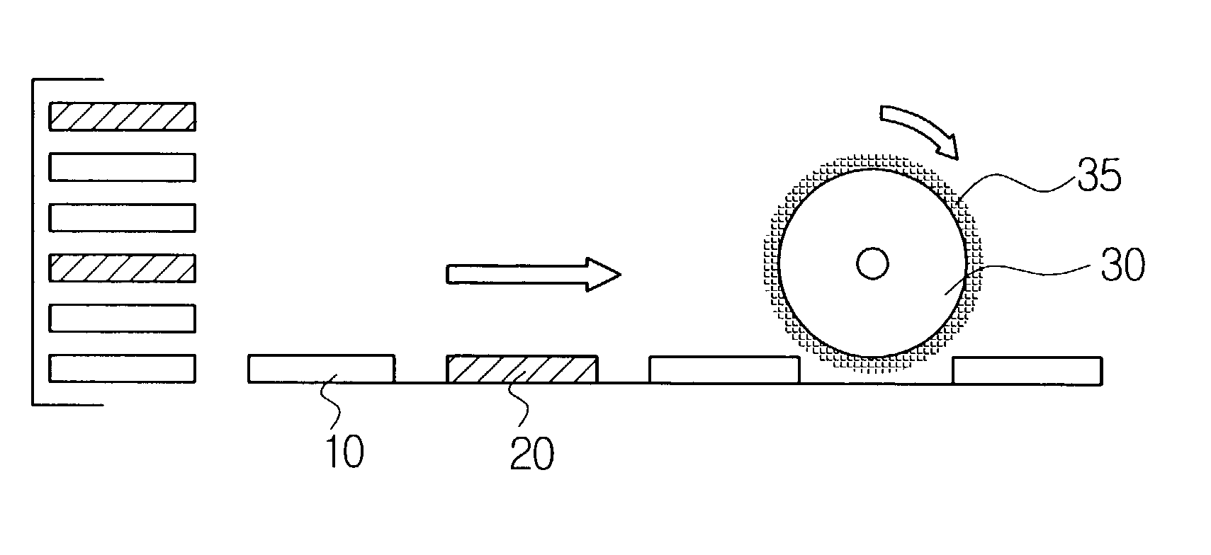
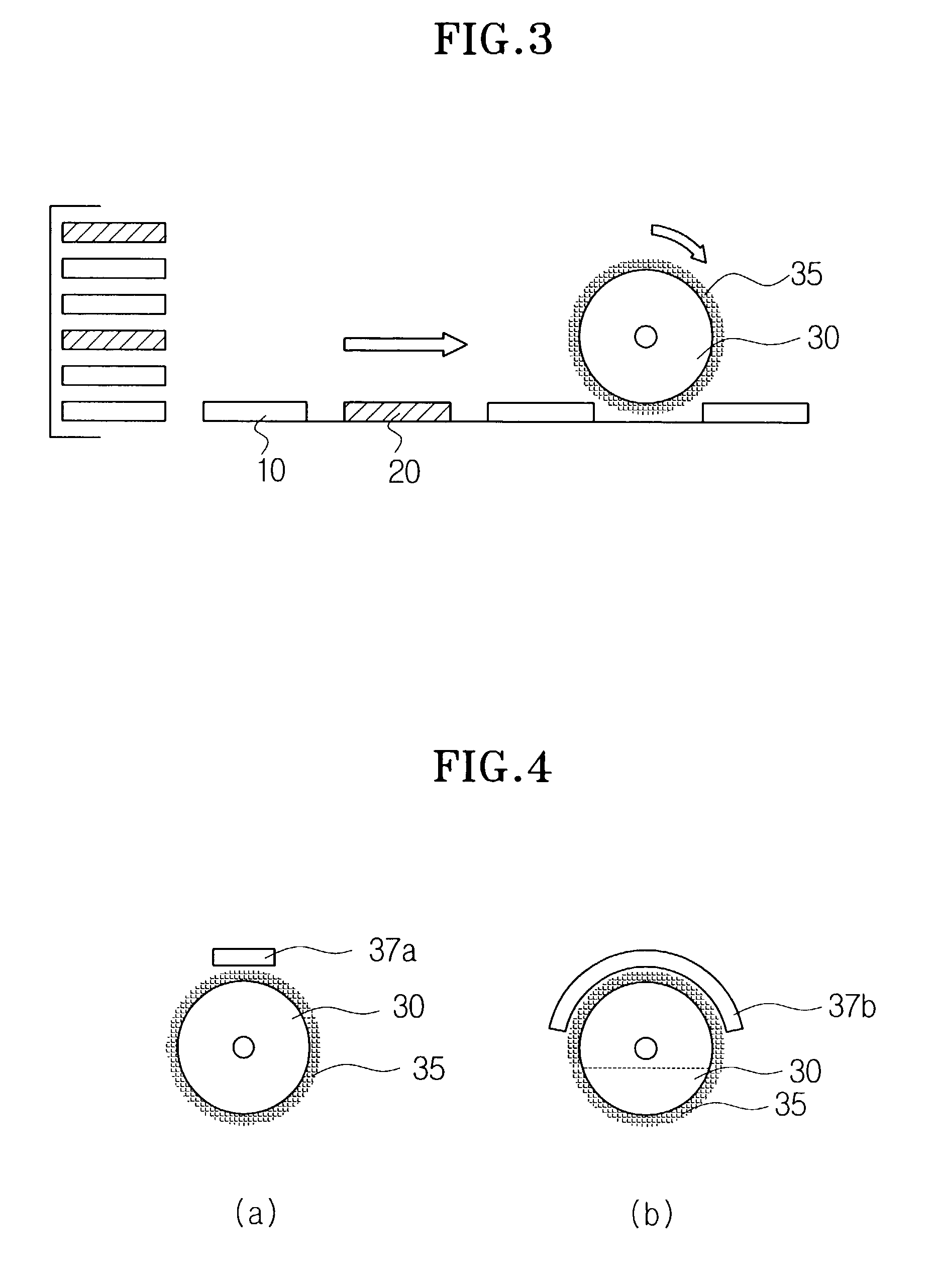
[0036]As shown in FIG. 3, in order to realign a rubbing cloth, realigning test substrates 20 are first inserted between several mass production substrates 10. At this time, the number of the realigning test substrates 20 and a material of forming the test substrates can be suitably selected without departing the sensible scope of the present invention.

[0037]Moreover, the rubbing machine is formed in such a manner that the rubbing roll 30 having a rubbing cloth 35 attached thereon rotates while it runs on the substrates 10 under a desired pressure. In this case, since the portion of the rubbing cloth 35 coming in contact with the substrates 10 corresponds to the portion of the roll 30, the remaining portion of the rubbing cloth can be sufficiently realigned.

[0038]As sh...


PUM

PropertyMeasurementUnit
areaaaaaaaaaaa
contact areaaaaaaaaaaa
curved shapeaaaaaaaaaa

Abstract

The present invention relates to a rubbing machine with realigning functions for use in an LCD manufacturing process and also to a rubbing method which is conducted using the same. The rubbing machine is used to determine the direction of alignment by rubbing an alignment film coated on a substrate disposed on a stage. In this rubbing machine, an realigning section for realigning a rubbing cloth is disposed on the portion of a rubbing roll in such a manner that the realigning section be in contact with the rubbing cloth.

Description

BACKGROUND OF THE INVENTION[0001]1. Field of the Invention[0002]The present invention relates to a rubbing machine for use in a liquid crystal display manufacturing process. More particularly, the present invention relates to a rubbing machine for use in a liquid crystal display manufacturing process, and also to a rubbing method which is conducted using the same, in which the rubbing machine has a realigning function of a rubbing cloth and is suitable for use in a rubbing process involved in the manufacture of a liquid crystal display panel and for use in the fabrication of equipment for manufacturing a liquid crystal display.[0003]2. Description of the Prior Art[0004]A rubbing process, in which an alignment film coated on a substrate is rubbed with a cloth and the like to determine the direction of alignment, is a critical process in an LCD manufacturing process. Recently, in addition to twisted nematic (TN) mode, various modes including in-plane switching mode, fringe field switc...

Claims


Application Information

Patent Timeline
Patent Type & Authority Patents(United States)
IPC IPC(8): B24B7/00G02F1/13G02F1/1337
CPCG02F1/133784G02F1/1337
Inventor PARK, CHI HYUCKKIM, HYANG YULPARK, TAE KYU
Owner BOE HYDIS TECH
Why Eureka
Try Eureka