
Method for designing pointing of antenna of deep space probe

A technology for deep space detectors and design methods, applied in the field of deep space exploration, can solve problems such as increased weight and power consumption, complex pointing control calculations, and narrow beams of directional antennas

Active Publication Date: 2015-02-25
BEIJING INST OF SPACECRAFT SYST ENG
View PDF5 Cites 22 Cited by
  • Summary
  • Abstract
  • Description
  • Claims
  • Application Information

AI Technical Summary

Problems solved by technology

Due to the narrow beam of the directional antenna, considering the orbit changes of the earth and the moon, it is generally necessary to use a two-axis rotating tracking mechanism to achieve continuous long-term pointing to the earth and the moon, but the use of a rotating mechanism will increase weight and power consumption, and pointing control computationally complex issues

Method used


Image

  • Method for designing pointing of antenna of deep space probe
  • Method for designing pointing of antenna of deep space probe
  • Method for designing pointing of antenna of deep space probe

Examples


Embodiment Construction

[0033] The present invention will be described in detail below in conjunction with specific examples.

[0034] Pre-defined coordinate system: The detector control coordinate system is defined as the inertial spindle coordinate system.

[0035] Earth-centered J2000 inertial coordinate system: the origin of the coordinates is at the center of mass of the earth, the reference plane is the J2000.0 flat equatorial plane, the Z axis points north to the north pole of the flat equatorial plane, the X axis points to the J2000.0 flat vernal equinox, and the Y axis is composed of X and Z axes Right-angle right-handed system.

[0036] Mechanical coordinate system of the detector: +X axis is the orientation axis towards the sun, +Y axis points to a specific structural feature of the detector, and is perpendicular to the +X axis, +Z, +X axis and +Y axis form a right-handed coordinate system.

[0037] Earth-moon transfer segment and phase around the moon:

[0038] The ground calculates the...


PUM


Abstract

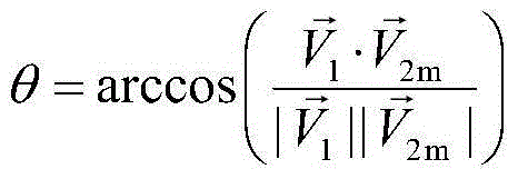
The invention provides a method for designing pointing of an antenna of a deep space probe. The method particularly comprises the steps that firstly, the expression (please see the formula in the specification) of the probe-geocentre position vector on a mechanical coordinate system is calculated; secondly, according to the V2m, the included angle theta between the full-direction antenna direction vector and a probe-control station is calculated; thirdly, when the included angle theta is larger than the maximum allowable angle gamma, the probe rotates around the +x axis of a mechanical coordinate system, and gains of the rotated full-direction antenna meet the requirements of an upper link and a down link. According to the method, the antenna rotates around the counterglow directional axis by a certain angle, and therefore continuity of the measuring and control process is ensured; the antenna using operation caused by ground switching is reduced; the ground operation complexity is reduced; and meanwhile, the antenna is located in the section with the large gains, and the link channel allowance is improved.

Description

technical field [0001] The invention relates to the technical field of deep space detection, in particular to a method for designing the antenna pointing of a deep space detector. Background technique [0002] During the earth-moon transfer and the flight around the moon, the deep space probe usually adopts a fixed axis of the mechanical system (defined as +X axis below) to orient itself to the sun in the normal cruising mode and in the state of not imaging the moon, so as to ensure the solar wing method The line direction is parallel to the sunlight direction. In this case, if the installation orientation of the omnidirectional TT&C antenna can be parallel to the ±X-axis, whether the detector rotates around the X-axis will not affect the angle between the antenna axis and the detector-TTCS, so that the cruising flight of the detector will not be affected. There are no constraints required for poses. Under such conditions, the detector will adopt a slow-spin attitude, whic...

Claims


Application Information

Patent Timeline
Patent Type & Authority Applications(China)
IPC IPC(8): B64G1/66
Inventor 董捷孙泽洲李飞马继楠吴学英张熇
Owner BEIJING INST OF SPACECRAFT SYST ENG
Learn More