Cleaning Apparatus and Method

a technology of cleaning apparatus and aqueous solution, which is applied in the direction of washing machines with receptacles, textiles and papermaking, other washing machines, etc., can solve the problems of increasing the difficulty of reducing the water level (and hence energy and detergent) in a pure aqueous process, and increasing the cost and environmental impact of the process. , to achieve the effect of improving the distribution of rinsing water,

Active Publication Date: 2012-12-06
XEROS LTD
View PDF9 Cites 38 Cited by
  • Summary
  • Abstract
  • Description
  • Claims
  • Application Information

AI Technical Summary

Benefits of technology

[0059]On completion of the wash cycle, feeding of solid particulate cleaning material into the rotatably mounted cylindrical cage ceases and the speed of rotation of the cage is initially increased in order to effect a measure of drying of the cleaned substrate, thereby generating G forces of between 10 and 1000, more specifically between 40 and 400. Typically, for a 98 cm diameter cage, rotation is at a speed of up to 800 rpm in order to achieve this effect. Subsequently, rotation speed is reduced and returned to the speed of the wash cycle so as to allow for removal of the solid particulate cleaning material.
[0060]Optionally, following said bead removal operation, said method may additionally comprise a rinsing operation, wherein additional water may be added to said rotatably mounted cylindrical cage in order to effect complete removal of any additional cleaning agent employed in the cleaning operation. Water may be added to said cylindrical cage via said addition port mounted on said access door. Again, addition may optionally be carried out by means of a spray head in order to achieve better distribution of the rinsing water in the washload. Alternatively, said addition may be via the separating means, or by overfilling the second, lower chamber of said apparatus with water such that it enters the first, upper chamber and thereby partially submerges said rotatably mounted cylindrical cage and enters into said cage. Following rotation at the same speed as during the wash cycle, water is removed from said cage by allowing the water level to fall as appropriate and, whatever method of rinse water addition is employed, the speed of rotation of the cage is then increased so as to achieve a measure of drying of the substrate. Typically, for a 98 cm diameter cage, rotation is at a speed of up to 800 rpm in order to achieve this effect. Subsequently, rotation speed is reduced and returned to the speed of the wash cycle, thereby allowing for final removal of any remaining solid particulate cleaning material. Said rinsing and drying cycles may be repeated as often as desired.

Problems solved by technology
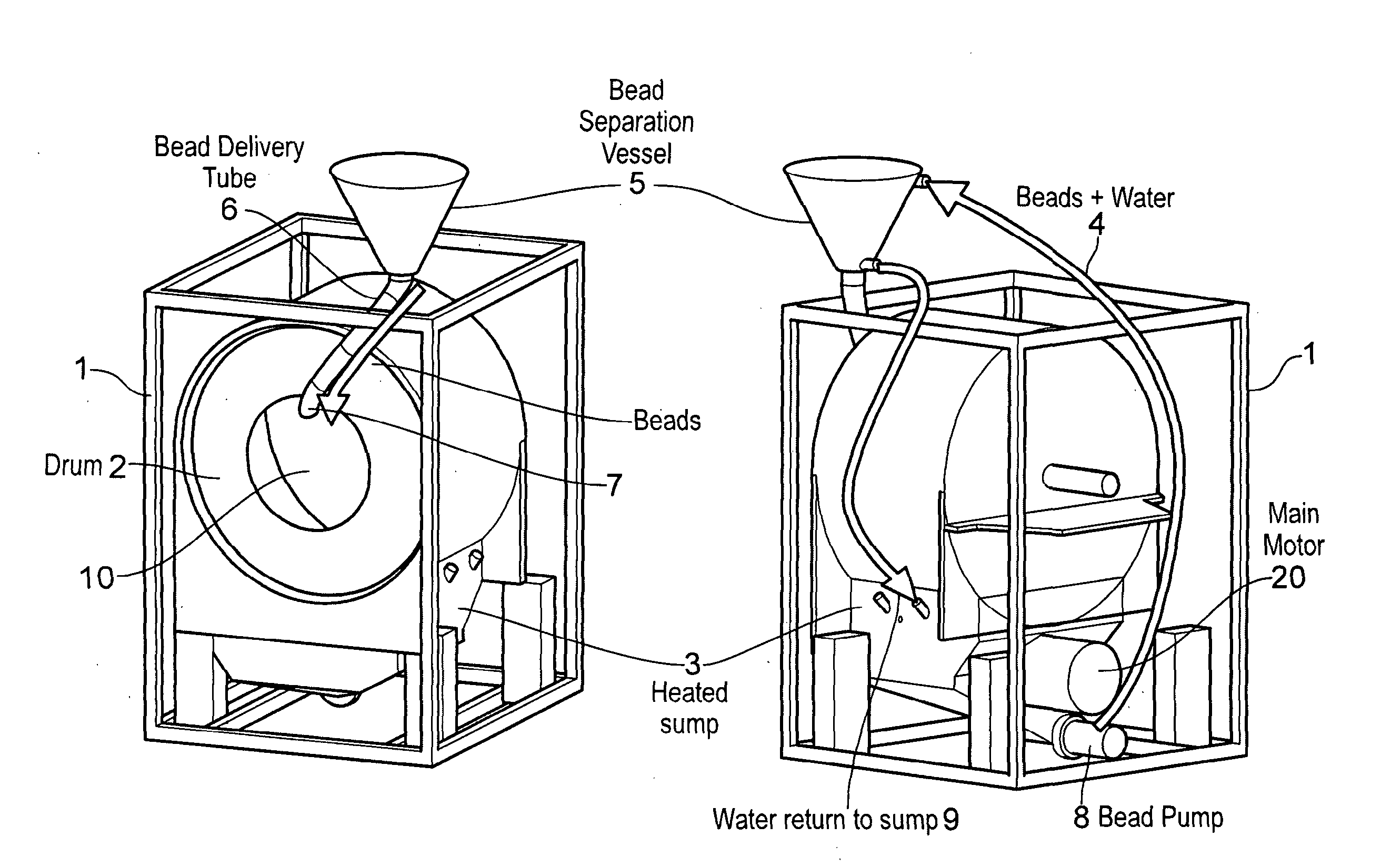
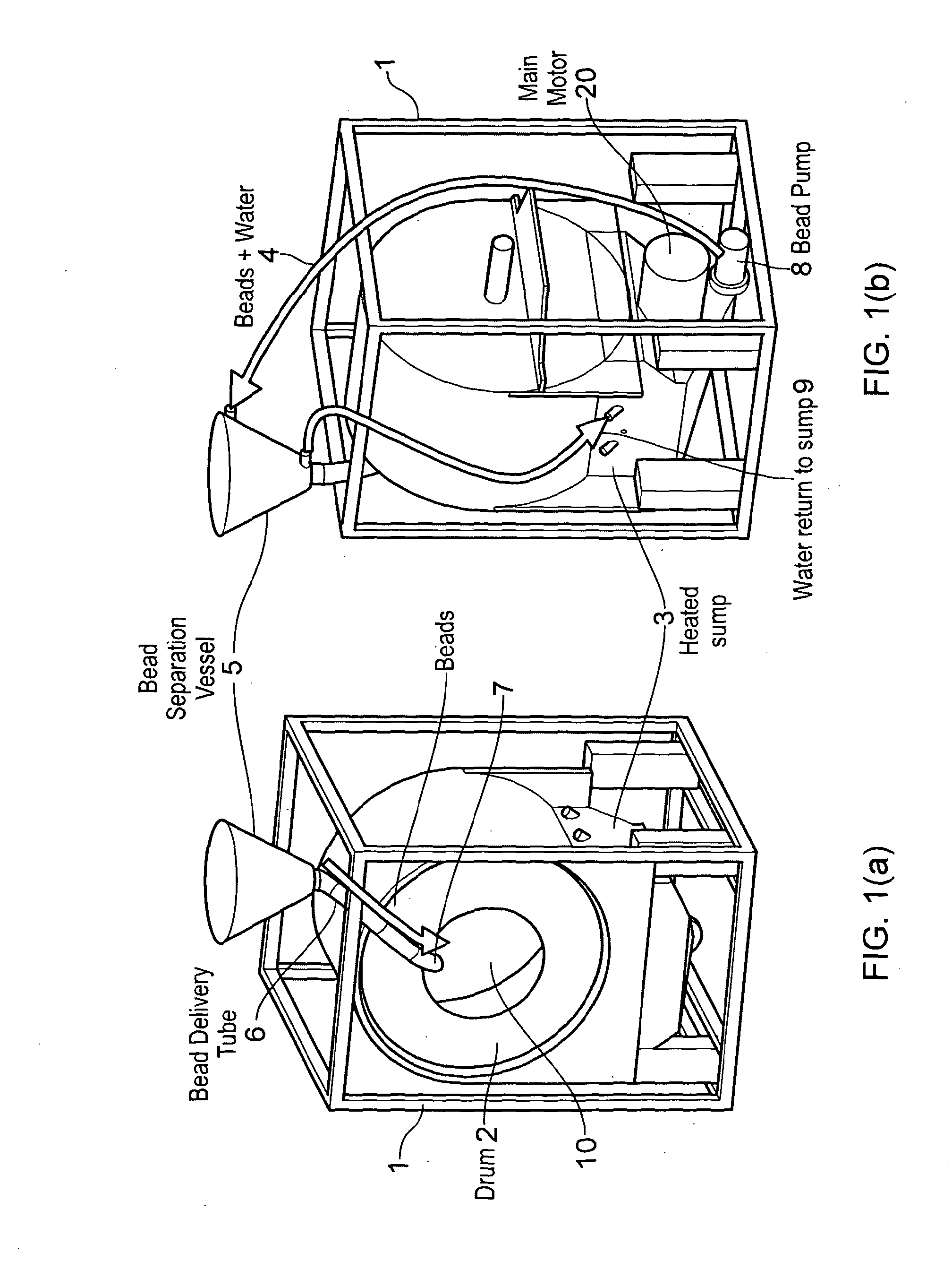
On the assumption that the desired level of cleaning is achieved, the efficacy of such processes is usually characterised by their levels of consumption of energy, water and detergent.
The downstream effect of reduced water and detergent consumption is also significant, as this minimises the need for disposal of aqueous effluent, which is both extremely costly and detrimental to the environment.
The key issue, however, concerns water consumption, as this sets the energy requirements (in order to heat the wash water), and the detergent dosage (to achieve the desired detergent concentration).
For domestic washing in particular there are defined wash performance standards specifically designed to discourage the use of such higher levels in practice, in addition to the obvious cost penalties which are associated with such usage.
However, as already mentioned, it is becoming increasingly difficult to reduce the water (and, hence, energy and detergent) levels in a purely aqueous process, due to the minimum requirement to wet the fabric thoroughly, the need to provide sufficient excess water to suspend the soil removed in an aqueous liquor and, finally, the need to rinse the fabric.
However, increasing the mechanical action in a purely aqueous washing process has certain associated drawbacks.
Fabric creasing readily occurs in such processes, and this acts to concentrate the stresses from mechanical action at each crease, resulting in localised fabric damage.
Many of these technologies are, however, technically complex and not readily suited to domestic applications, in particular.

Method used


Image

  • Cleaning Apparatus and Method
  • Cleaning Apparatus and Method
  • Cleaning Apparatus and Method

Examples


example 1

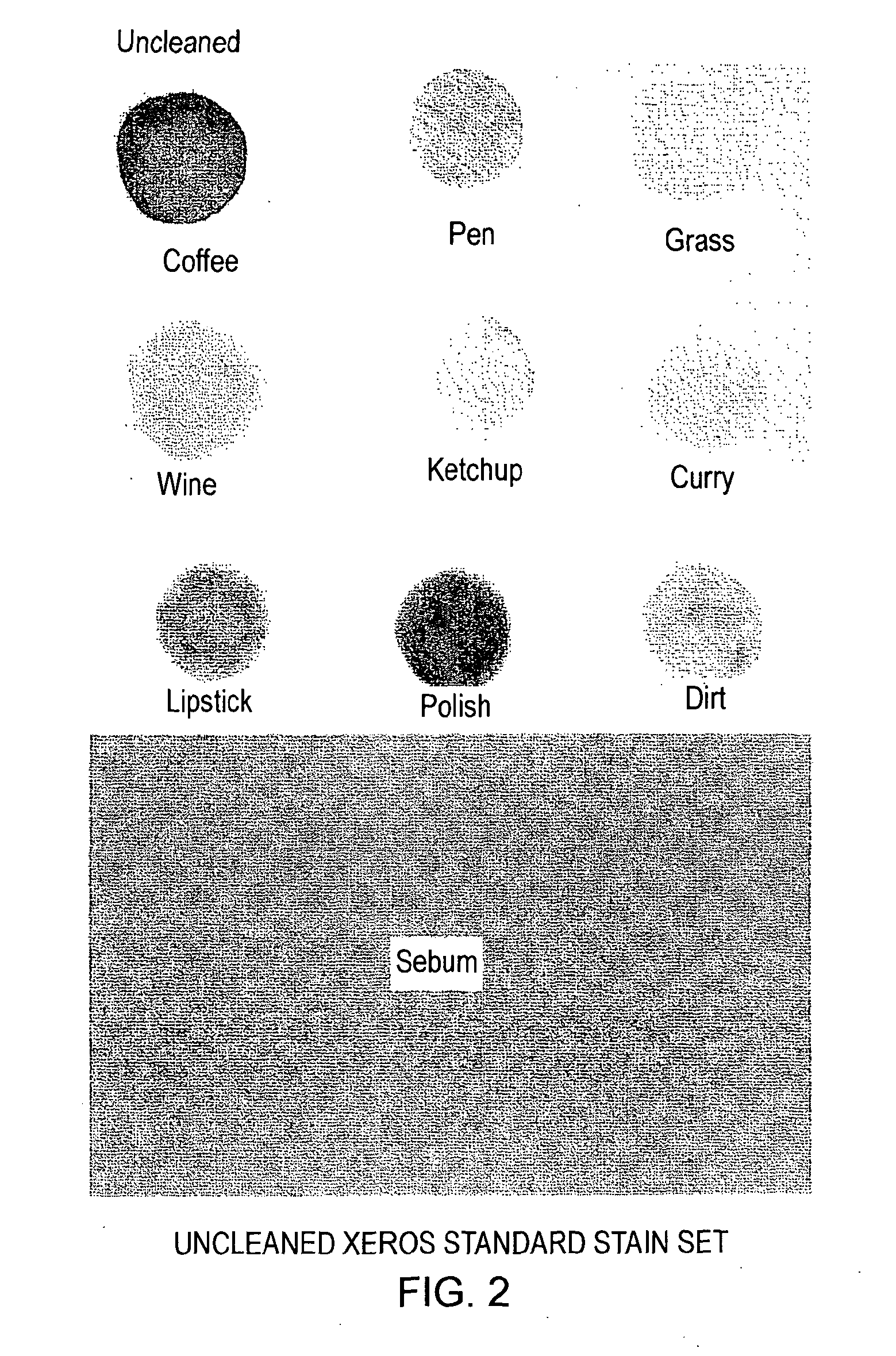
[0119]Woven cotton fabric (194 gm−2, Whaleys, Bradford, U.K.) was stained with coffee, lipstick, ball point pen, tomato ketchup, boot polish, grass, vacuum dirt, curry sauce and red wine following the methods described below:

[0120](i) Coffee

[0121]10 g of Morrisons® Full Roast coffee powder was dissolved in 50 ml distilled water at 70° C. A 1 cm3 aliquot of the ensuing solution was applied to the fabric using a synthetic sponge, within the confines of a 5 cm diameter circular plastic template; the stained fabric was then allowed to dry at ambient temperature (23° C.), after which the fabric was aged prior to use, by storage in the dark for 4 days.

[0122](ii) Lipstick

[0123]Revlon® Super Lustrous lipstick (copper frost shade) was applied to the fabric using a synthetic sponge to provide a uniform coverage within the confines of a 5 cm diameter circular plastic template. The fabric was then aged following the procedure recounted for coffee.

[0124](iii) Ball Point Pen

[0125]A black Paper Ma...


PUM


Abstract

The invention provides an apparatus and method for use in the cleaning of soiled substrates, the apparatus comprising: (a) housing means (1), having: (i) a first upper chamber having mounted therein a rotatably mounted cylindrical cage, and (ii) a second lower chamber (3) located beneath the cylindrical cage; (b) at least one recirculation means (4); (c) access means (10); (d) pumping means (8); (e) a multiplicity of delivery means (6), wherein the rotatably mounted cylindrical cage comprises a drum (2) comprising perforated side walls, wherein up to 60% of the surface area of the side walls comprises perforations, and the perforations comprise holes having a diameter of no greater than 25.0 mm. The method involves cleaning the soiled substrate by treatment of the moistened substrate with a formulation comprising solid particulate cleaning material and wash water, the method being carried out using the apparatus of the invention. The apparatus and method find particular application in the cleaning of textile fabrics.

Description

FIELD OF THE INVENTION[0001]The present invention relates to the aqueous cleaning of substrates using a cleaning system which requires the use of only limited quantities of energy, water and detergent. Most particularly, the invention is concerned with the cleaning of textile fibres and fabrics by means of such a system, and provides an apparatus adapted for use in this context.BACKGROUND TO THE INVENTION[0002]Aqueous cleaning processes are a mainstay of both domestic and industrial textile fabric washing. On the assumption that the desired level of cleaning is achieved, the efficacy of such processes is usually characterised by their levels of consumption of energy, water and detergent. In general, the lower the requirements with regard to these three components, the more efficient the washing process is deemed. The downstream effect of reduced water and detergent consumption is also significant, as this minimises the need for disposal of aqueous effluent, which is both extremely c...

Claims


Application Information

Patent Timeline
Patent Type & Authority Applications(United States)
IPC IPC(8): D06F23/02D06F39/02D06L1/20D06F35/00
CPCD06F35/00D06F23/02D06F35/005D06F37/304D06F39/04
Inventor JENKINS, STEPHEN DEREKKENNEDY, FRAZER JOHN
Owner XEROS LTD
Why Eureka
Try Eureka