Debris removing system for use in X-ray light source

a technology debris removal system, which is applied in the field of x-ray light source, can solve the problems of reducing the scattering particles, and reducing the efficiency of lithography using ultraviolet light, and achieves the effect of superior debris removal and good utilization efficiency of euv ligh

Inactive Publication Date: 2005-03-15
CANON KK
View PDF11 Cites 37 Cited by
  • Summary
  • Abstract
  • Description
  • Claims
  • Application Information

AI Technical Summary

Benefits of technology

It is accordingly an object of the present invention to provide a debris removing system by which both a sup

Problems solved by technology

However, miniaturization of semiconductor devices has advanced quickly, and there is a limitation in the lithography using ultraviolet light.
However, in the laser plasma method as an example of the EUV light source method, although EUV light is produced in response to projection of large-intensity pulse laser light upon a target, the pulse laser projection creates, on the other hand, scattered particles, being called debris.
This may cause contamination of or damage to optical elements, and may lead to a decrease of the reflectivity.
It has been recognized that the inconveniences caused by debris

Method used


Image

  • Debris removing system for use in X-ray light source
  • Debris removing system for use in X-ray light source
  • Debris removing system for use in X-ray light source

Examples


Embodiment Construction

Referring now to the drawings, an exposure apparatus 10, which uses a debris removing system 100 according to an embodiment of the present invention, will now be described. In the drawings, the same reference numerals denote corresponding elements.

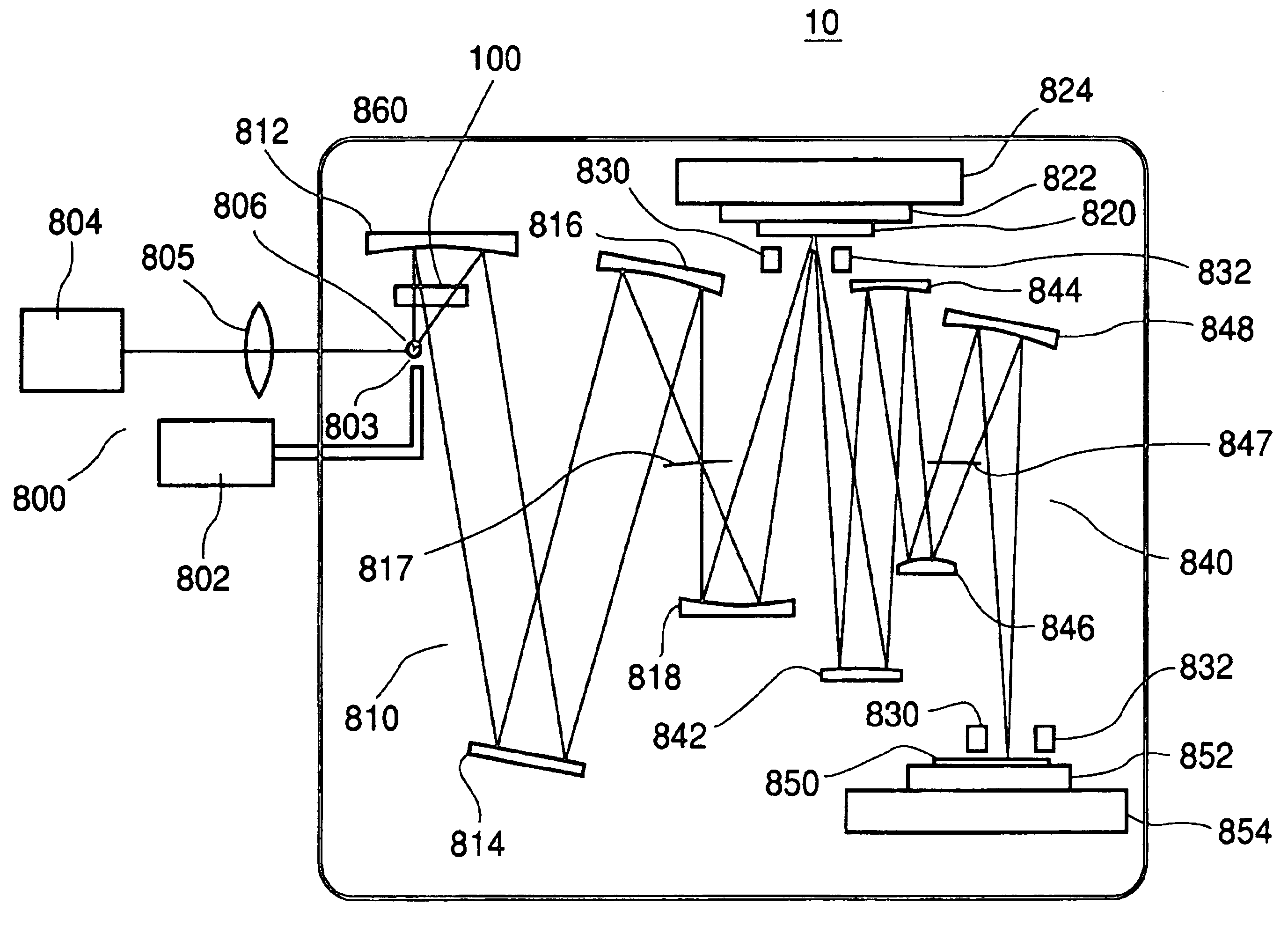
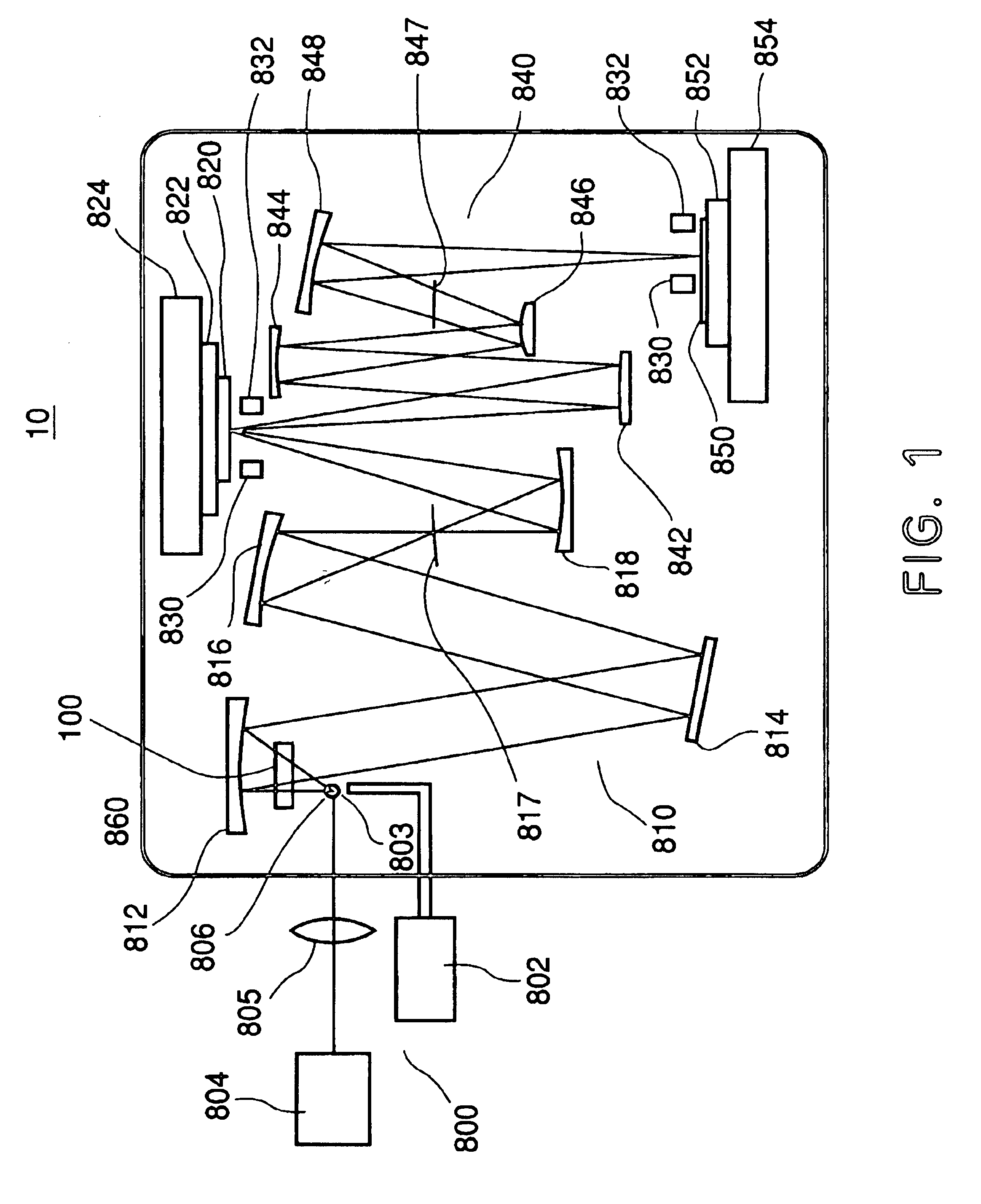
FIG. 1 is a schematic view of the exposure apparatus 10. The exposure apparatus 10 is an X-ray projection exposure apparatus in which step-and-scan exposure is to be carried out by use of EUV light (for example, having a wavelength of 13.4 nm) as exposure light.

As shown in FIG. 1, the exposure apparatus 10 comprises an EUV light source 800, a debris removing system 100, an illumination optical system 810, a reflection type reticle (reflection type mask) 820, an alignment optical system 830, a projection optical system 840, a reticle stage 824, and a wafer stage 854. The components from the debris removing system to the wafer stage 854 are accommodated in a vacuum container 860.

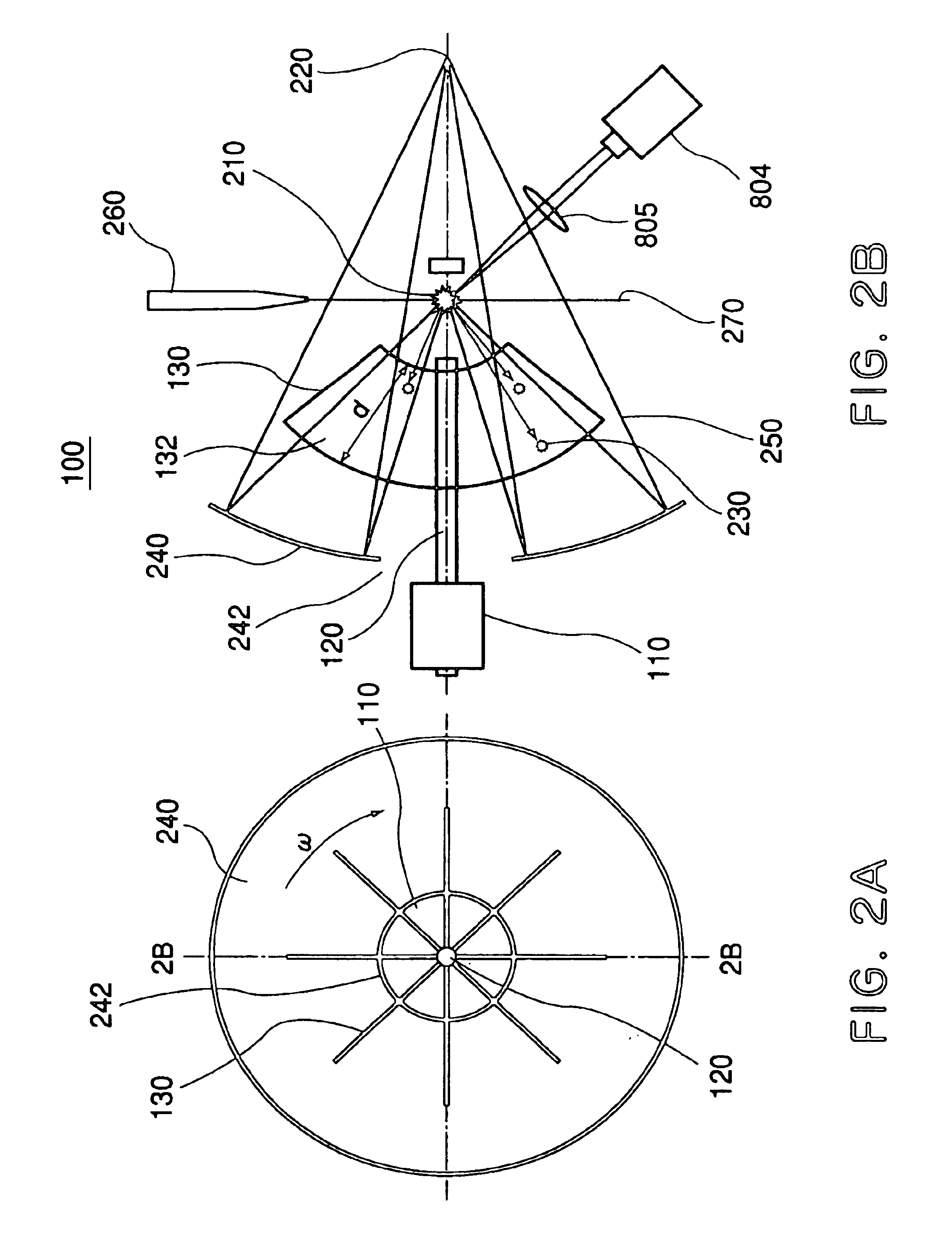
The EUV light source 800 of this embodiment uses laser plasma, ...


PUM


Abstract

A debris removing system prevents debris from being scattered from an X-ray source. The debris removing system includes an attracting unit, disposed between a light emission point of the X-ray source and the optical system, for attracting debris. The attracting unit has an attracting surface parallel or approximately parallel to an axis passing through the light emission point. The debris removing system further includes a rotation unit for rotating the attracting unit about the axis. This debris removing system assures a superior debris removing effect and a good EUV light utilization efficiency, being compatible with each other.

Description

FIELD OF THE INVENTION AND RELATED ARTThis invention relates generally to an X-ray projection exposure apparatus or X-ray proximity exposure apparatus for transferring a fine pattern in semiconductor manufacture. More particularly, the invention concerns an X-ray light source which can be used in such an exposure apparatus, for example.In accordance with recent requirements for further reduction in size and thickness of electronic instruments, the need for further minimization of a semiconductor device to be incorporated into an electronic instrument increases more and more. Conventionally, as a lithographic method for the manufacture of semiconductor devices, there is a reduction projection exposure method using ultraviolet rays. In such reduction projection exposure, the smallest size to be transferred is proportional to the wavelength of light used for the transfer process, and it is inversely proportional to the numerical aperture of a projection optical system. Thus, for transf...

Claims


Application Information

Patent Timeline
IPC IPC(8): G03F7/20H05G2/00A61B5/117G03F1/22G03F1/24H01L21/027
CPCB82Y10/00G03F7/70033H05G2/001G21K1/04G21K1/043G03F7/70916
Inventor OGUSHI, NOBUAKIWATANABE, YUTAKAMIYAKE, AKIRA
Owner CANON KK
Why Eureka
Try Eureka