Manhole cover stop mechanism

a manhole cover and stop mechanism technology, applied in the direction of artificial islands, building roofs, foundation engineering, etc., can solve the problems of severe hazard to vehicles and pedestrian traffic when opening to a catch basin or manhole, and achieve the effect of convenient operation and convenient installation

Active Publication Date: 2011-02-22
NEENAH FOUNDRY
View PDF9 Cites 37 Cited by
  • Summary
  • Abstract
  • Description
  • Claims
  • Application Information

AI Technical Summary

Benefits of technology

[0009]In this position, the protruding one end of the locking member may be aligned with a fixed abutment located above the protruding end and preventing complete removal of the cover, although able to move up to a limited extent due to a clearance between the stop member one end and the abutment which creates an annular gap allowing venting of the gases created in an explosion.
[0012]The stop mechanism is advantageously combined with a manhole cover to prevent the cover from being completely blown free of a surface manhole vault structure or to be removed by an unauthorized person.

Problems solved by technology

If the covers are removed by thieves or vandals, the opening to a catch basin or manhole presents severe hazard to vehicles and pedestrian traffic.
Removal of these covers by vandals or scavengers has become an increasing problem which has created an urgent need for some means for preventing unauthorized removal of the covers.
That mechanism relies on a spring return to retract the stop member, but due to the possibility of corrosion, causing increased resistance to movement of the parts of the mechanism, it is desirable to not rely on a spring operation of the retraction release as the mechanism since it may be exposed to the elements for many years.

Method used


Image

  • Manhole cover stop mechanism
  • Manhole cover stop mechanism
  • Manhole cover stop mechanism

Examples


Embodiment Construction

[0023]In the following detailed description, certain specific terminology will be employed for the sake of clarity and a particular embodiment described in accordance with the requirements of 35 USC 112, but it is to be understood that the same is not intended to be limiting and should not be so construed inasmuch as the invention is capable of taking many forms and variations within the scope of the appended claims.

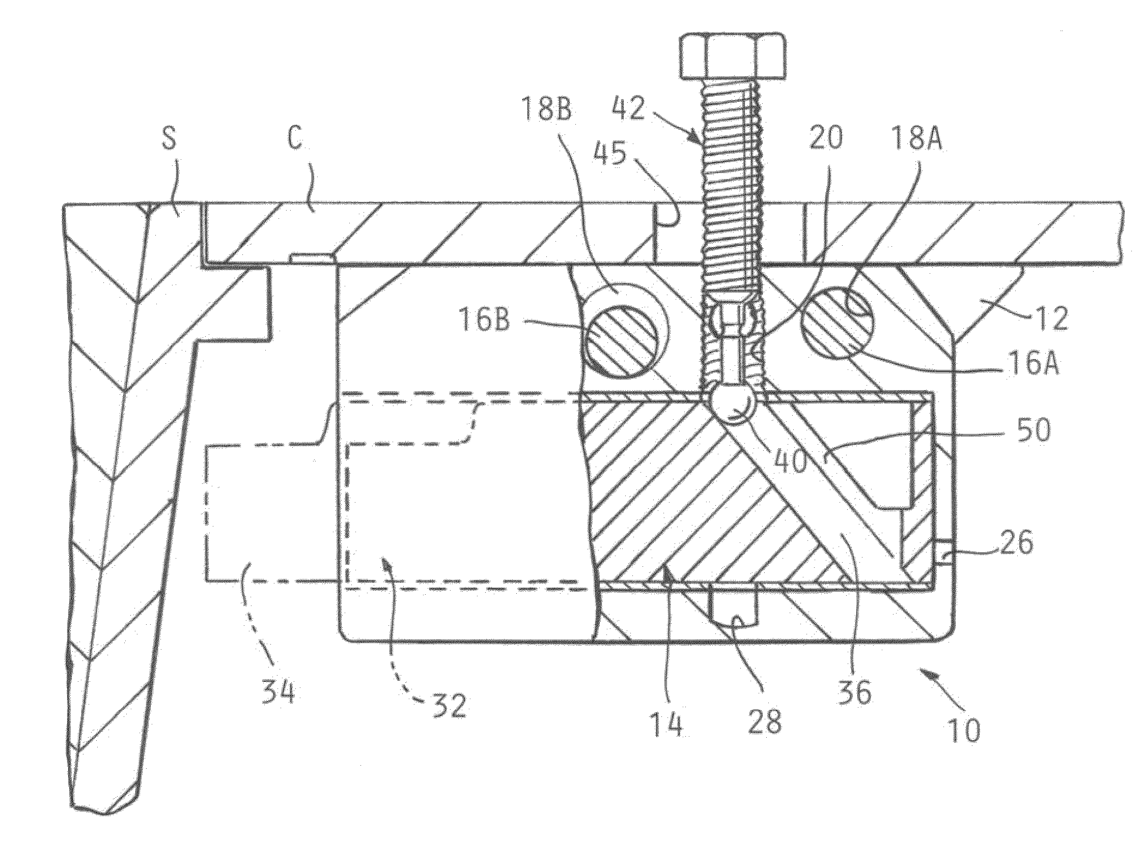
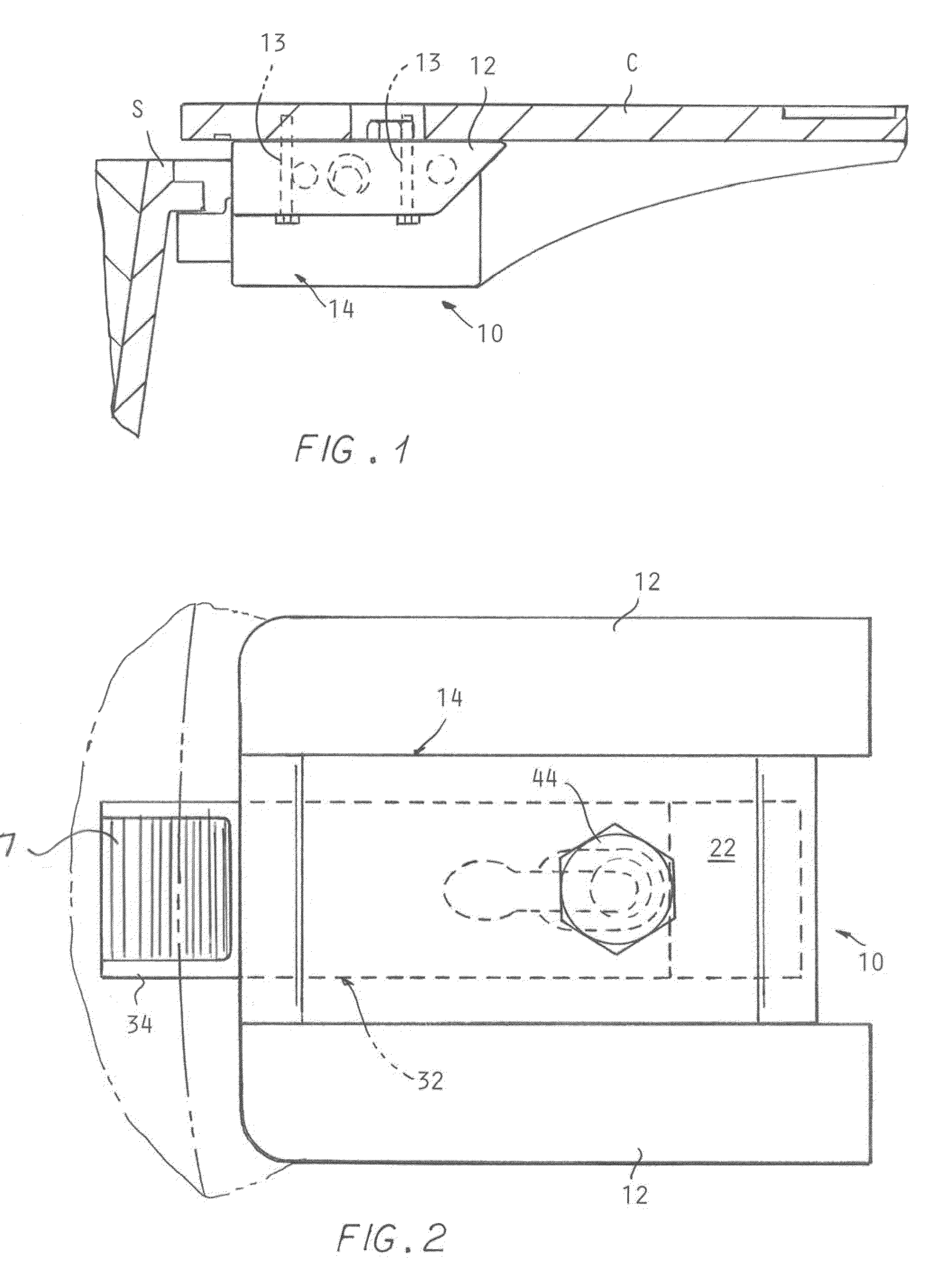
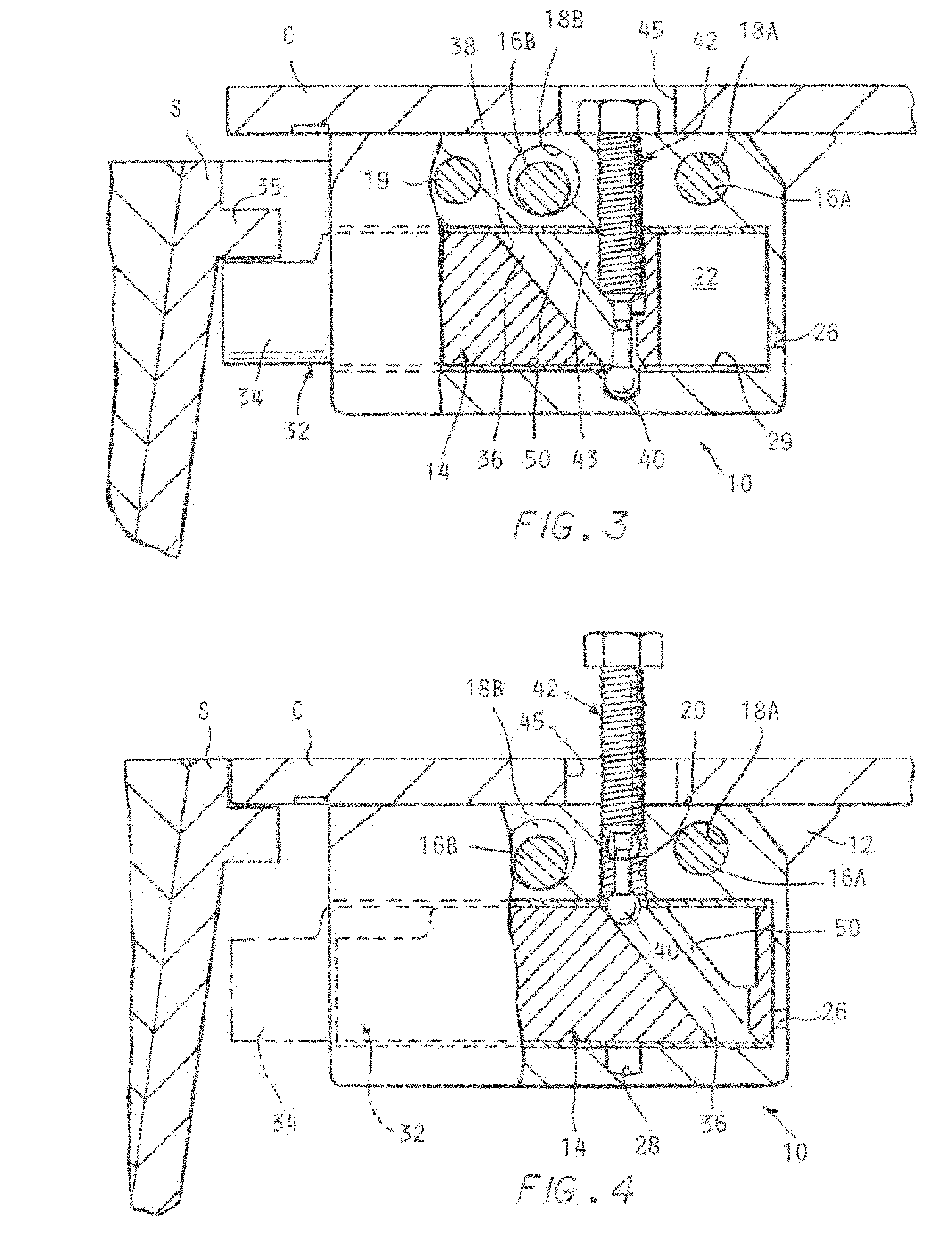
[0024]As shown in the drawing Figures, an embodiment of a stop mechanism 10 according to the invention is shown, suspended between a pair of side rails 12 attached to the underside of the cover C with bolts 13 received in the threaded holes in the underside of the cover C in a generally similar manner as the mechanism shown in U.S. Pat. No. 7,484,908, incorporated herein by reference. The stop mechanism 10 includes a holder body 14, having a longitudinal passage 15 is formed therein. The holder body 14 may be attached to the underside of a manhole cover C fit into an ope...


PUM


Abstract

A stop mechanism advantageously combined with a manhole cover includes a holder body having a passage which slidably receives a stop member able to be cammed in and out upon advance or retraction of a threaded drive member having an enlarged tip engaged with a down sloping channel formed in the stop member. Upper sides of the channel engage the tip upon reversal of the drive member to cam the stop member back into the holder body. The stop member when extends prevents removal of the cover from being blown completely free of the manhole vault structure in the event of an explosion.

Description

CROSS REFERENCE TO RELATED APPLICATIONS[0001]This application is a continuation in part of U.S. application Ser. No. 12 / 357,525 filed on Jan. 22, 2009 now U.S. Pat. No. 7,712,995 which is a division of U.S. patent application Ser. No. 11 / 761,711 filed on Jun. 12, 2007, now U.S. Pat. No. 7,484,908. which claims benefit of U.S. provisional patent application No. 60 / 921,975 filed on Apr. 6, 2007 and U.S. provisional patent application No. 60 / 889,553 filed on Feb. 13, 2007 and No. 60 / 812,757 filed on Jun. 12, 2006. This application also claims benefit of U.S. provisional application No. 61 / 131,754 filed on Jun. 11, 2008.BACKGROUND OF THE INVENTION[0002]The present invention concerns retractable stop mechanisms and more particularly such mechanisms for preventing unauthorized removal of covers for catch basins and manholes installed in roadways for access to utilities, i.e., water, gas, communications, electricity, etc. These covers are provided in order to keep out debris but also to pr...

Claims


Application Information

Patent Timeline
Patent Type & Authority Patents(United States)
IPC IPC(8): E02D29/14
CPCE02D29/1427E02D29/1436
Inventor STADLER, DAVID
Owner NEENAH FOUNDRY
Why Eureka
Try Eureka