Blood clot removal device, system, and method

a technology of blood clot removal and a system, applied in the direction of prosthesis, wound drain, transportation and packaging, etc., can solve the problems of blood clots being triggered, severe damage to other parts of the body, and the heart cannot pump enough blood to meet the body's needs, etc., to achieve the removal of blood clots, short cleaning cycles, and rapid acceleration of the first piston

Active Publication Date: 2010-12-23
FORSELL PETER
View PDF16 Cites 38 Cited by
  • Summary
  • Abstract
  • Description
  • Claims
  • Application Information

AI Technical Summary

Benefits of technology

[0012]In one embodiment, the cleaning device comprises a first piston, with preferably is provided with a first recess in an outer end portion thereof to collect blood clots removed from the filter. By providing the first piston with a plurality of channels for accommodating the filter in an extended position of the first piston, it can surround the filter, ensuring essentially complete removal of blood clots therefrom. This is preferably effected if the first piston is movable in a direction perpendicular to the direction of the blood flow passageway.
[0041]The blood clot removal device is preferably programmable from outside the patients body. By adding the steps of sensing a physical parameter of the patient or a functional parameter of the device, and sending sensing information to an internal control unit adapted for regulating said blood clot removal device, performance is improved.

Problems solved by technology

All such implants have an associated risk of triggering blood clots.
Such clots may become loose and may create severe damages at other parts of the body.
When a person has heart failure, his or her heart can't pump enough blood to meet the body's needs.
However, the potential risks are serious, including the risk of having blood clots in the arteries leading from the heart.

Method used


Image

  • Blood clot removal device, system, and method
  • Blood clot removal device, system, and method
  • Blood clot removal device, system, and method

Examples


Embodiment Construction

[0066]In the following a detailed description of preferred embodiments of the present invention will be given. In the drawing figures, like reference numerals designate identical or corresponding elements throughout the several figures. It will be appreciated that these figures are for illustration only and are not in any way restricting the scope of the invention. Thus, any references to direction, such as “up” or “down”, are only referring to the directions shown in the figures. Also, any dimensions etc. shown in the figures are for illustration purposes.

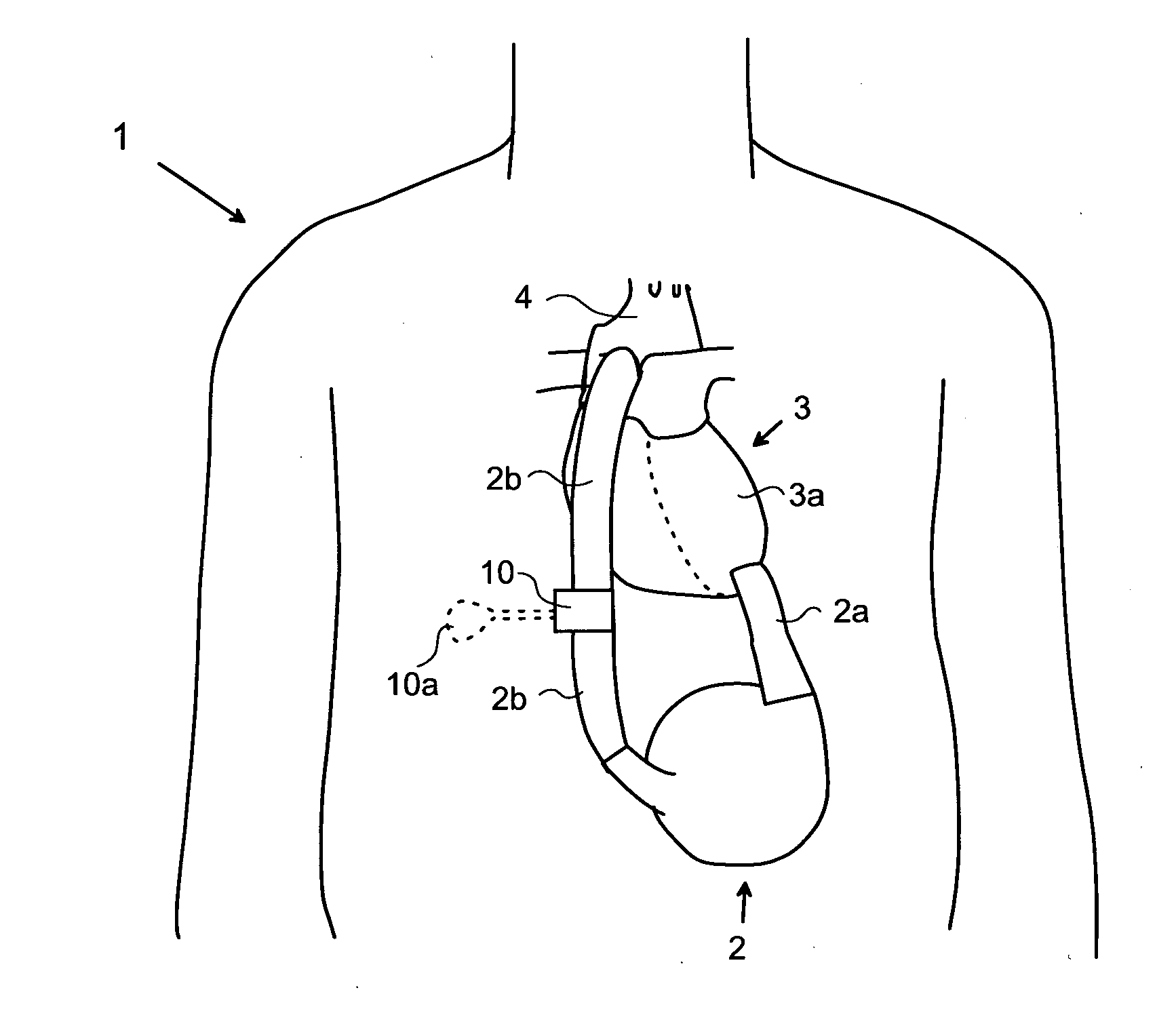
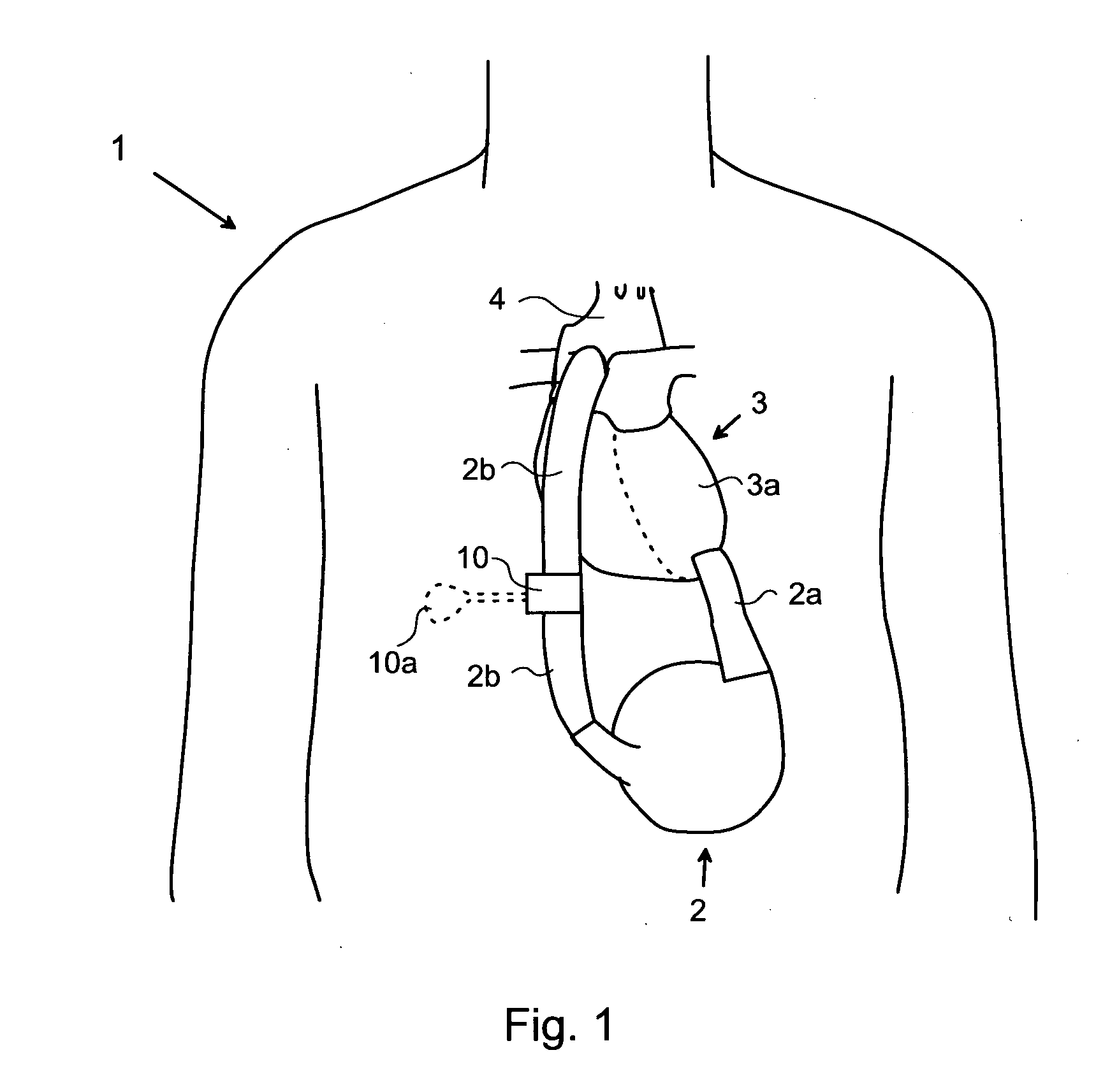
[0067]FIG. 1 shows a patient 1 having an implanted heart pump 2. The implanted heart pump 2 is connected to the left ventricle 3a of the patient's heart 3 by means of a first tube 2a. The heart pump 2 is also connected to the aorta, generally designated 4, of the patient 1 by means of a second tube 2b. In this way, during operation the heart pump supplements or replaces the blood pumping operation of the patient's heart 3.

[0068]A ...


PUM

PropertyMeasurementUnit
distanceaaaaaaaaaa
distanceaaaaaaaaaa
distanceaaaaaaaaaa

Abstract

A blood clot removal device for removing blood clots from the vascular system of a patient is implantable in the patient's body. The blood clot removal device comprises a blood flow passageway, a filter provided in the blood flow passageway for filtering blood clots, and a cleaning device for cleaning the filter. By means of such blood clot removal device and system, the risk of blood clots reaching sensitive areas of the patient's body, such as the brain, is reduced.

Description

FIELD OF INVENTION[0001]The present invention relates generally to a device and a system implantable in a blood flow passageway of a human or mammal patient for removing blood clots, and more particularly to a system for removing blood clots in a vascular system of the patient, one example being a heart pump system. The invention also relates to a method of removing blood clots.BACKGROUND[0002]Today many implants are provided where the blood comes into contact with foreign material. All such implants have an associated risk of triggering blood clots. Such clots may become loose and may create severe damages at other parts of the body. Blood clots reaching the brain are the most dangerous ones and implants in the heart region may therefore be a first priority (although not limited to) of a blood clot removal system. One example of such implants and one example of use for the blood clot removal system may be heart help pumps. When a person has heart failure, his or her heart can't pum...

Claims


Application Information

Patent Timeline
Patent Type & Authority Applications(United States)
IPC IPC(8): A61M29/00
CPCA61M2205/3523A61M1/0072B01D46/0065B01D46/0064A61F2250/0001A61F2250/0002A61M1/82A61M1/79A61M2205/7554B01D46/68B01D46/681A61M1/72A61M27/002A61F2/0036A61M1/71A61F2/482A61F2/484B01D46/66B01D46/79B01D46/86B01D46/88B01D46/90A61M60/122A61M60/00A61M60/857A61M60/871A61M60/50A61M27/006A61M2027/004A61M2205/10A61M2205/3331A61M2210/1021A61M2210/1078
Inventor FORSELL, PETER
Owner FORSELL PETER
Why Eureka
Try Eureka