Turbo system and method of installing

a technology of a turbocharger and a mounting method, which is applied in the direction of mechanical equipment, machines/engines, and non-fuel substance addition to fuel, etc., can solve the problems of damage to the bearings and shafts of the turbocharger, failure of the turbocharger, and “dry” conditions, so as to improve the performance and efficiency of the turbocharger, reduce the temperature of the turbocharger, and increase the consistency of the flow of gases

Inactive Publication Date: 2007-05-17
STS TURBO
View PDF16 Cites 12 Cited by
  • Summary
  • Abstract
  • Description
  • Claims
  • Application Information

AI Technical Summary

Benefits of technology

[0017] As the compressor impeller spins, outside air is pulled into the compressor and fed to the engine intake, throttle body or carburetor. In order to minimize debris entering the compressor, an air filter is coupled to the air intake of the compressor. In one embodiment, the air filter is located in a position where it will not be exposed to the elements that may otherwise require premature replacement of the air filter once air flow is significantly restricted by the collection of various particles and away from the heat of the engine.
[0032] In another embodiment, a pump controller is provided to help match the speed of the pump to the oil removal needs of the turbocharger. That is, as oil pressure within the system increases with increased engine rpm, more oil will enter the turbocharger. At lower engine rpms, the oil removal requirements for the pump are decreased with the decrease of oil pressure on the pressure side of the vehicle's oiling system. Because a pump in accordance with the present invention may produce pump noise during operation, the controller can significantly reduce such pump noise when engine rpms are relatively low, and increase the pump speed as needed along with engine speed. Furthermore, the noise produced by the increased engine speed from the engine itself will help drown out or overcome the noise produced by the pump at such higher engine rpms.

Problems solved by technology

Any pressure build up or restriction of the oil outlet consequently restricts inlet oil flow and results in a lower volume of lubrication across the turbocharger bearings causing damage to the bearings and shaft of the turbocharger and eventually a turbocharger failure.
This conventional turbocharger installation method results in a “dry” condition upon engine startup.
Thus, the turbocharger can begin spinning at relatively high rpms without adequate lubrication until lubricating oil finally reaches the turbocharger.
Spinning the turbocharger without adequate lubrication can cause increased wear of bearings and other components and result in premature failure of the turbocharger.
Such heat surely shortens the life of a turbocharger, as heated components tend to wear more rapidly as lubricants are typically less effective at higher temperatures.
Conventional turbocharger installations are quite difficult due to the lack of space under the hood of most modern vehicles.
Such relocation of equipment significantly adds to the expense of conventional turbocharger installations.
The addition of all of these extra components and extra plumbing required to mount a traditional turbocharger system under the hood severely overcrowds an already crowded engine compartment making it extremely difficult to do the standard maintenance and any repair work required to keep the vehicle in good condition and greatly increases the labor costs associated with any future maintenance or repairs needed to be performed.
In addition, extreme under-hood temperatures are generated by turbochargers sometimes causing the cooling system of the vehicle to exceed its capabilities and require that a cooling system upgrade be performed as well.
Furthermore, these extreme under-hood temperatures can effect various plastic and rubber engine and vehicle components by causing them to fail.
In point of fact, turbocharger temperatures can become so extreme during aggressive driving conditions that the turbocharger bearings can be detrimentally affected unless the turbocharger is allowed to cool down for a period of time with the engine idling before the engine is shut off.
An intercooler, however, causes a restriction in the flow of charge air creating a pressure differential across the intercooler.
Moreover, compressing the air to a higher pressure causes further heating of the already hot air.
Thus, the added demands on the turbocharger compressor further increase the operating temperature of the turbocharger.
As with the installation of a turbocharger, the installation of intercooler components is expensive and sometimes difficult to mount because of their size and the limited space available in front of the radiator of modern vehicles.
This exposes the expensive and fragile intercooler to damaging road debris that can clog and restrict the flow of the air through the intercooler, reducing its cooling capacity and efficiency.

Method used


Image

  • Turbo system and method of installing
  • Turbo system and method of installing
  • Turbo system and method of installing

Examples


Embodiment Construction

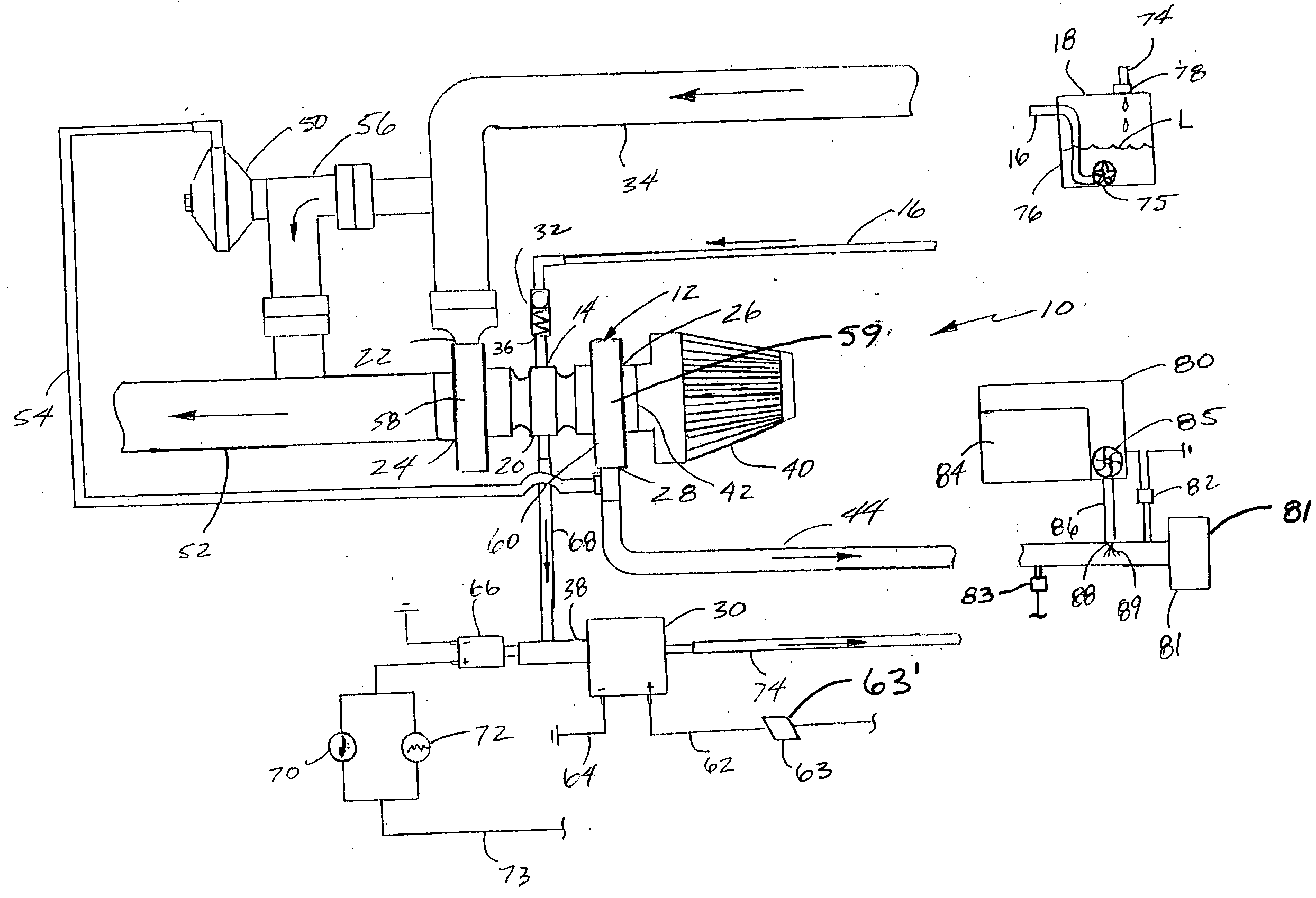
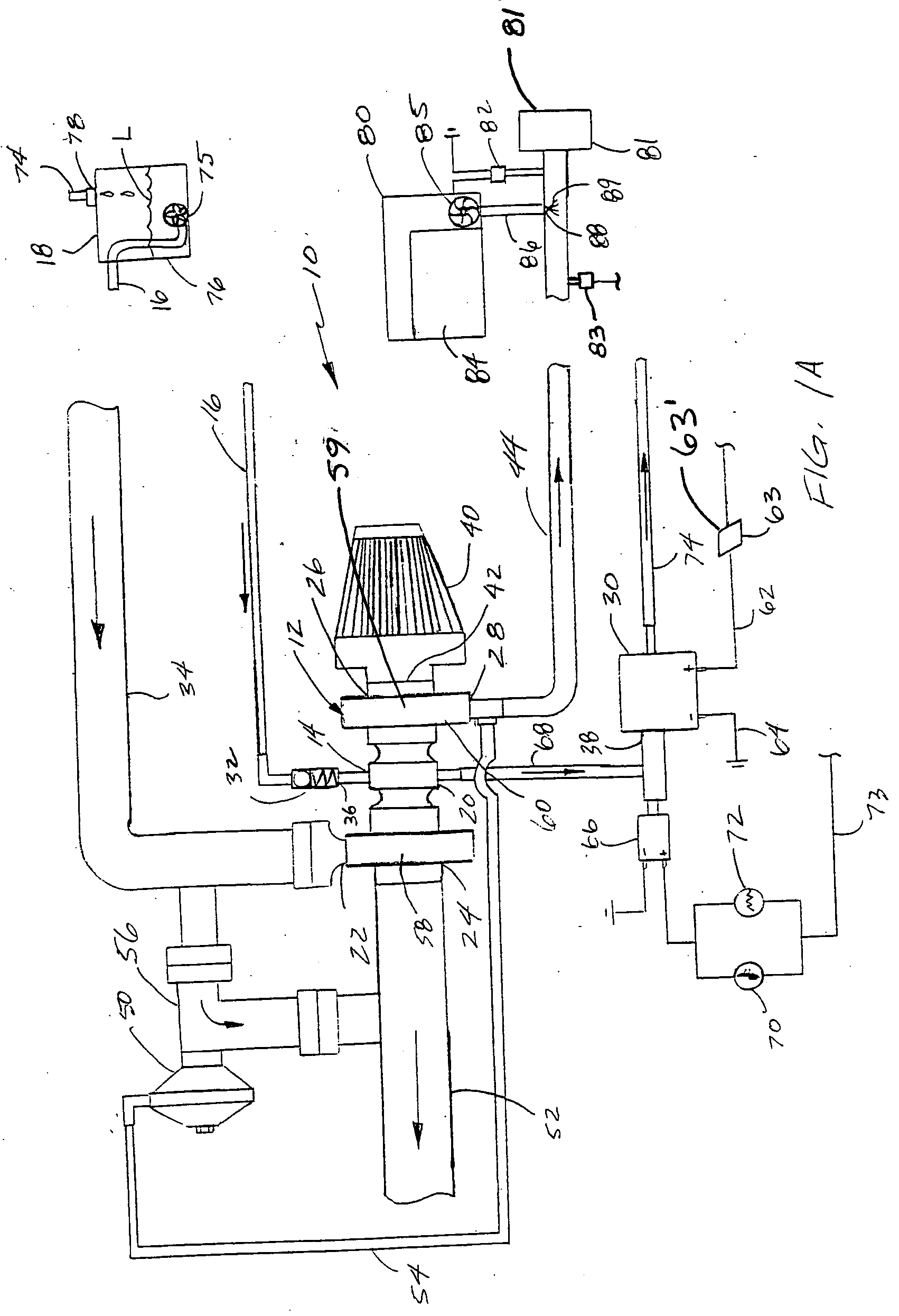
[0043] Referring to FIG. 1A, a turbocharger system, generally indicated at 10, for use with a combustion engine (not shown), is comprised of a turbocharger 12 having an oil inlet 14 configured for being coupled to the pressure side 16 of the oil pump 75 of an oiling system 18; and an oil outlet 20. The turbocharger 12 also includes an exhaust inlet 22 and outlet 24 on the turbine and an ambient air inlet 26 and a charge air outlet 28 on the compressor. An oil pump 30 in fluid communication with the oil outlet 20 is configured for being in fluid communication with the oiling system 18. A pressure driven check valve 32 is coupled to the oil inlet 14 of the turbocharger 12 and in fluid communication therewith. The check valve 32 is configured to prevent the flow of oil from the pressure side 16 of the oiling system 18 into the turbocharger when the pressure on the pressure side 16 of the oiling system 18 drops below a predetermined level. For example, a 5-psi check valve will close whe...


PUM

PropertyMeasurementUnit
temperaturesaaaaaaaaaa
pressureaaaaaaaaaa
exhaust pressureaaaaaaaaaa

Abstract

A turbocharger system for a combustion engine and method of installing a turbocharger system includes a turbocharger having an oil inlet configured for being coupled to a pressure side of an oiling system and an oil outlet, an exhaust inlet and outlet and an air charge inlet and outlet. An oil pump is connected to the oil outlet of the turbocharger and is further connected to the oiling system. A pressure driven check valve is coupled to the oil inlet of the turbocharger to prevent oil from flowing into the turbocharger when the pressure on the pressure side of the oiling system drops below a predetermined level. The turbocharger system also includes mounting hardware for mounting the turbocharger to an exhaust pipe and away from the engine and at or below the oil level of the oiling system. In one embodiment, the method of installing the turbocharger system includes removing an existing muffler from the vehicle and mounting the turbocharger in the location of the existing muffler.

Description

BACKGROUND [0001] 1. Field of the Invention [0002] This invention relates generally to a turbo system used on a combustion-type engine for increasing the power of such an engine, and more specifically, to a turbo system and method of installing a turbo system on a vehicle, water craft, or other combustion-type, engine driven device or vehicle. [0003] 2. Background of the Invention [0004] Turbo systems in the automotive industry have been available for several decades. During that period of time, there have been many advances in such turbo systems including ways to increase their efficiency and increase their effect on engine horse power. [0005] A turbocharger utilizes the energy in the exhaust gases of an internal combustion engine to drive an impeller. The turbocharger consists of two impellers on opposite sides of a common shaft. One impeller in fluid communication with the exhaust gases of the engine functions as a fluid motor. The interaction of the flow and expansion of exhaust...

Claims


Application Information

Patent Timeline
Patent Type & Authority Applications(United States)
IPC IPC(8): F02B33/44F02B37/18F02B39/14
CPCF01M2001/123Y10T29/49716F01M2011/021F02B29/0481F02B33/44F02B37/02F02B37/18F02B37/186F02B39/14Y02T10/121Y02T10/144F02M25/0227F02M25/028Y10T29/49826Y10T29/49233Y10T29/49231F01M2011/0095Y02T10/12
Inventor SQUIRES, RICHARD K.
Owner STS TURBO
Why Eureka
Try Eureka