Continuous motion spin welding apparatus, system, and method

a technology of continuous motion and welding equipment, applied in the field of continuous motion spin welding equipment, system and method for assembling separate plastic parts, can solve the problems of limiting processing speed and increasing costs, requiring significant change-over time, and limiting processing speed

Inactive Publication Date: 2008-07-03
GRAHAM PACKAGING CO LP
View PDF10 Cites 40 Cited by
  • Summary
  • Abstract
  • Description
  • Claims
  • Application Information

AI Technical Summary

Problems solved by technology

Such production equipment typically requires indexing of individual parts, station-to-station stop and go processing, and / or batch processing, any or all of which can limit processing speeds and increase costs.
Furthermore, known spin welding devices often cannot accommodate containers of different sizes and / or can require significant change-over time for processing different size containers.

Method used


Image

  • Continuous motion spin welding apparatus, system, and method
  • Continuous motion spin welding apparatus, system, and method
  • Continuous motion spin welding apparatus, system, and method

Examples


Embodiment Construction

[0023]In describing the example embodiments of the present invention illustrated in the drawings, specific terminology is employed for the sake of clarity. However, the invention is not intended to be limited to the specific terminology so selected. It is to be understood that each specific element includes all technical equivalents that operate in a similar manner to accomplish a similar purpose. While specific exemplary embodiments are discussed, it should be understood that this is done for illustration purposes only. A person skilled in the relevant art will recognize that other components and configurations can be used without parting from the spirit and scope of the invention. Each patent document and / or non-patent literature publication cited herein is incorporated by reference in its entirety.

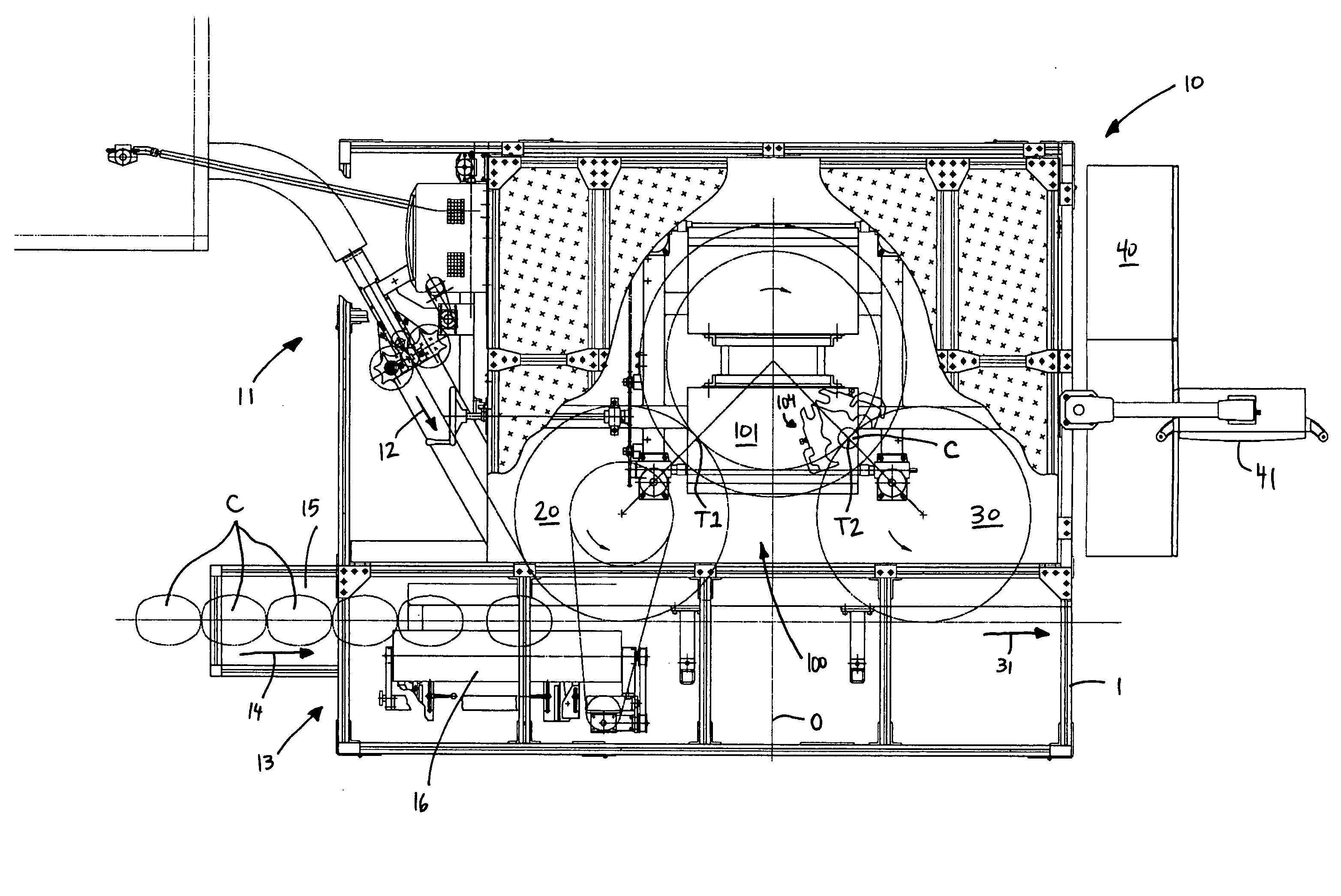
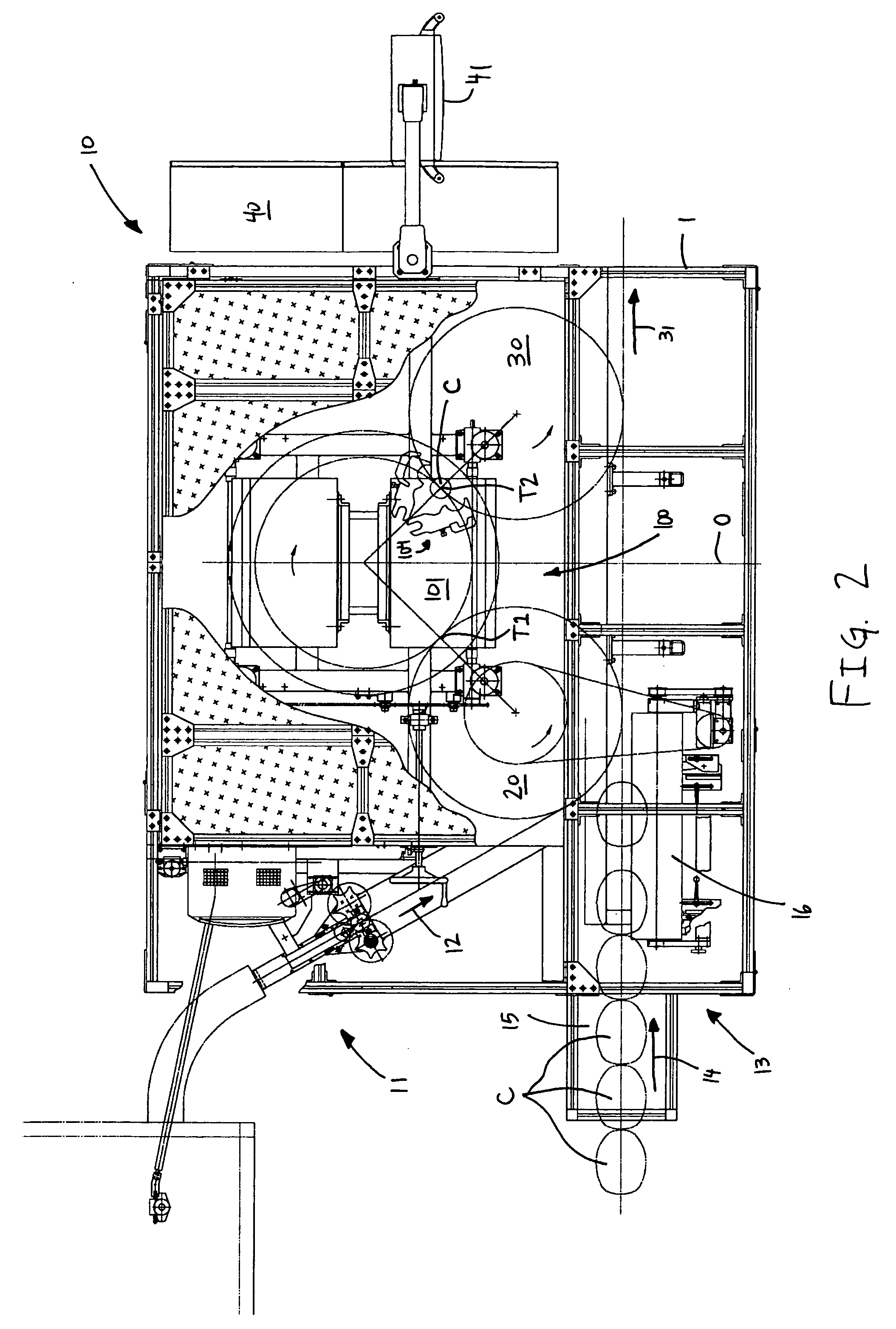
[0024]The invention relates to an apparatus and method for assembling separate plastic container parts. More specifically, the invention relates to a continuous motion spin welding appa...


PUM

PropertyMeasurementUnit
anglesaaaaaaaaaa
anglesaaaaaaaaaa
anglesaaaaaaaaaa

Abstract

An apparatus, system, and method for friction (spin) welding separate parts of a plastic component to one another. The apparatus includes a rotational drive assembly coupled to a turret assembly arranged to be rotationally driven thereby about a longitudinal axis. The turret assembly includes at least one drive mechanism and a plurality of spindle assemblies disposed circumferentially around the longitudinal axis, each spindle assembly defining a spindle axis and including coupled to a chuck configured to receive and hold a first part of the plastic component. The chuck is configured to move along the respective spindle axis to contact the first part of the plastic component with a second part of the plastic component. The at least one drive mechanism is configured to move the chuck and the first part relative to the second part at a speed sufficient to permanently bond the first part to the second part during rotation of the turret assembly.

Description

BACKGROUND[0001]1. Field of the Invention[0002]The invention relates generally to an apparatus, system, and method for assembling separate plastic parts. More specifically, the invention relates to a continuous motion spin welding apparatus, system, and method for spin welding separate parts of a plastic container to one another.[0003]2. Related Art[0004]In one widely-used commercial type of liquid containing and dispensing package, a pouring spout fitment having an integrally formed axially protruding dispensing spout is fixedly positioned on the neck of a container. For example, U.S. Pat. No. 4,671,421 to Reiber et al., the entirety of which is incorporated herein by reference, shows a plastic liquid containing and dispensing package which comprises a plastic blow molded container having an annular finish, an insert pour spout fitment positioned in the finish and interengaged with the internal surface of the finish and fixed thereto as by spin welding.[0005]Another example of this...

Claims


Application Information

Patent Timeline
Patent Type & Authority Applications(United States)
IPC IPC(8): B23K20/12
CPCB29C65/0672B29C65/7841B29C65/7844B29C65/7885B29C66/12463B29C66/80B29C66/81431B29L2031/712B29C66/53247B29C65/069B29C66/5344B29C66/81427B29C66/96B29C66/8322B29C66/93451B29C66/932B29C66/8246
Inventor HAWK, WESLEYGERHARDT, ERICKOHLER, DAVID
Owner GRAHAM PACKAGING CO LP
Why Eureka
Try Eureka