Hydrostatic arrangement for a spin welding machine and method of supporting spindle for the same

a welding machine and hydrostatic arrangement technology, applied in mechanical equipment, shafts and bearings, bearings, etc., can solve the problems of high torque, excessive wear, melting of end portions of parts during welding process,

Inactive Publication Date: 2012-03-22
ELKA PRECISION
View PDF30 Cites 7 Cited by
  • Summary
  • Abstract
  • Description
  • Claims
  • Application Information

AI Technical Summary

Problems solved by technology

The parts are forced together with axial force that generates high friction and high temperatures resulting in end portions of the parts melting during the welding process.
Because high speeds and extremely high forces are simultaneously required, the rotating shaft bearings have to satisfy very challenging and conflicting requirements: they have to endure high loads while at the same time be able to rotate at high speed.
Reducing load capacity of the bearing will allow higher speeds but will lead to excessive wear.
Inversely, bearings with increased load capacity can withstand high forces but will generally require higher torques, and consequently consume more energy and generate excessive heat.

Method used


Image

  • Hydrostatic arrangement for a spin welding machine and method of supporting spindle for the same
  • Hydrostatic arrangement for a spin welding machine and method of supporting spindle for the same
  • Hydrostatic arrangement for a spin welding machine and method of supporting spindle for the same

Examples


Embodiment Construction

[0013]A detailed description of one or more embodiments of the disclosed apparatus and method are presented herein by way of exemplification and not limitation with reference to the Figures.

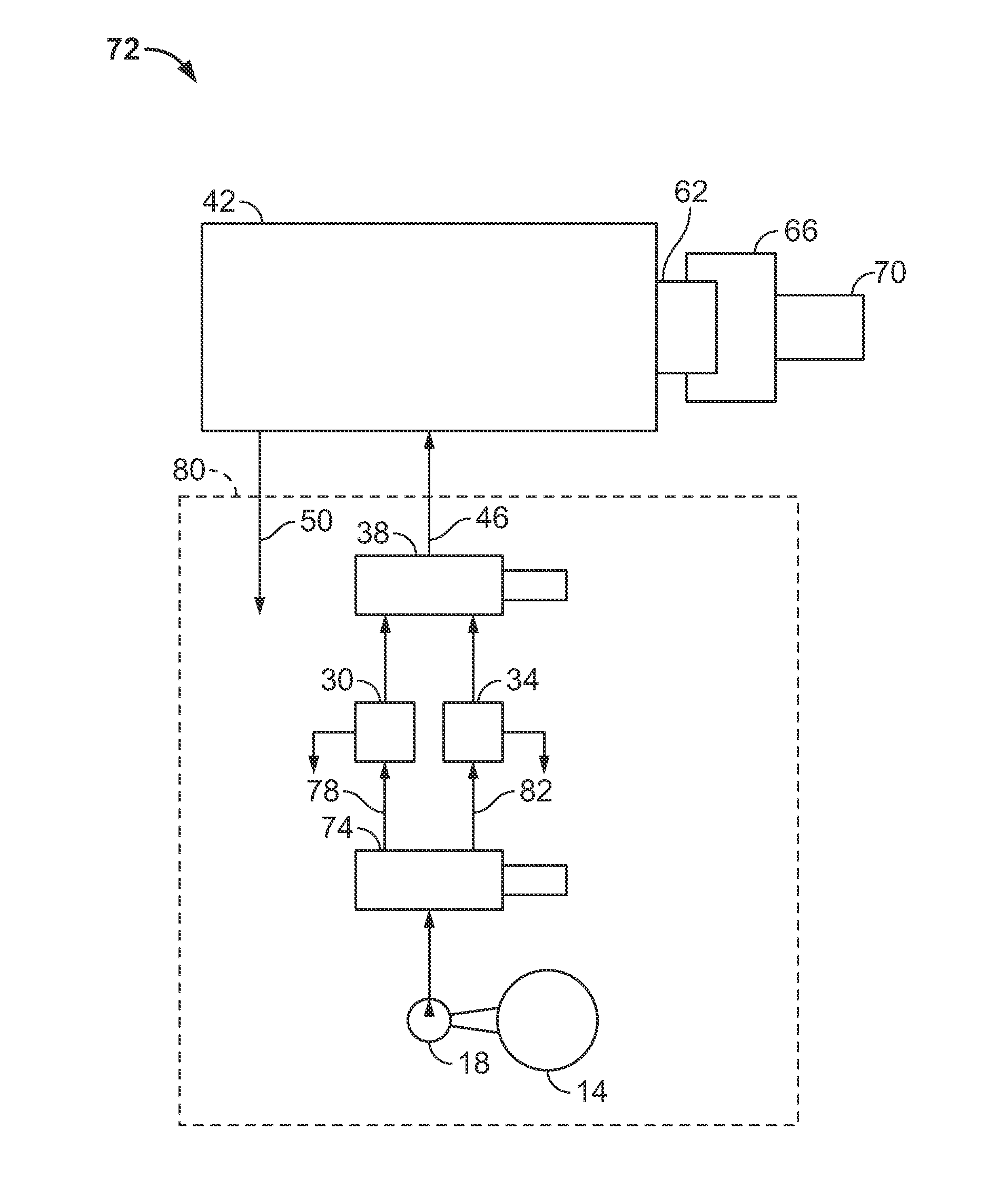
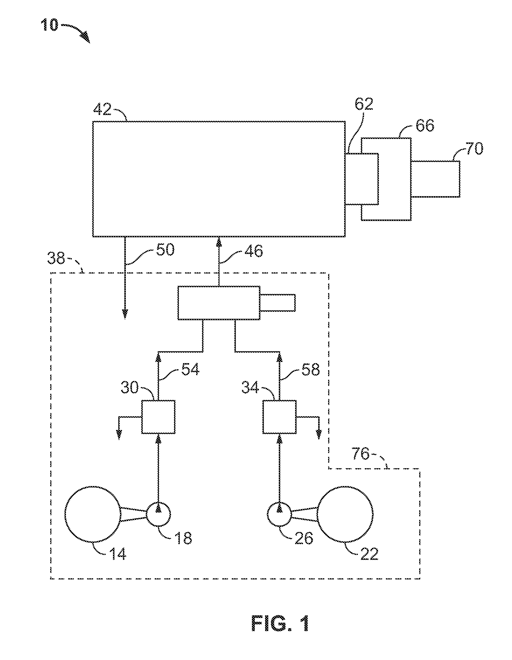
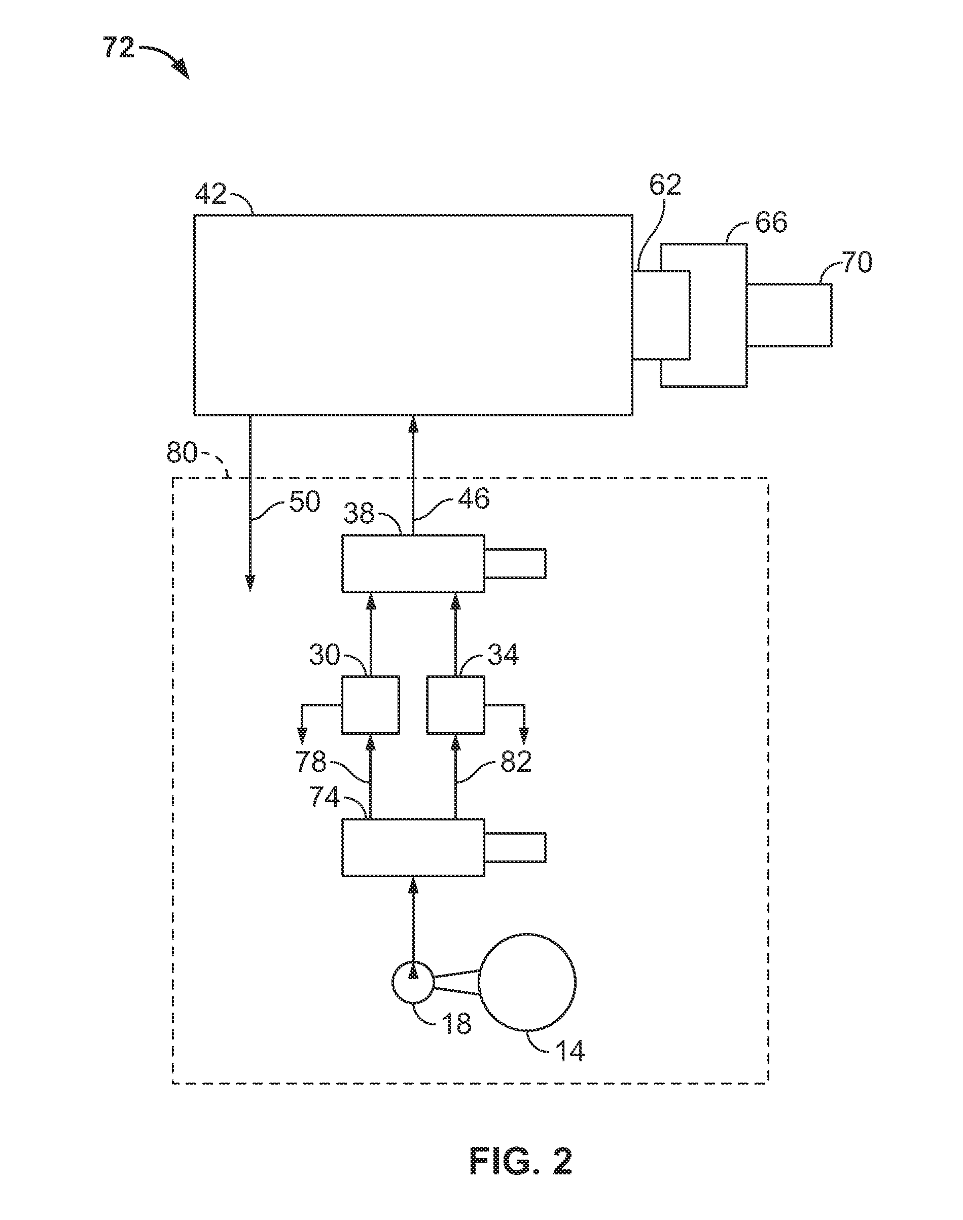
[0014]The current invention uses hydrostatic bearings to support a rotating shaft instead of the typical ball (or roller) bearings that are commonly employed in heavy-duty spin welding machines.

[0015]Increasing bearing fluid supply pressure can increase stiffness and load capacities of hydrostatic bearings without changing bearing sizes. In most current applications of hydrostatic bearings, however, the maximum supply pressure is limited by needed increases in flow rates and by increases in power required to pump fluid through the bearings. The pump power increases faster than the flow requirements, as it is proportional to the square of the supplied pressure.

[0016]Consequently an increased flow will typically require larger and more expensive components for the hydraulic power unit. Additionally...


PUM


Abstract

A hydrostatic arrangement for a spin welding machine includes, a spindle rotationally supported with at least one of a thrust hydrostatic bearing and a journal hydrostatic bearing, and a hydraulic unit configured to supply liquid to the at least one of a thrust hydrostatic bearing and a journal hydrostatic bearing at at least two different pressures.

Description

CROSS REFERENCE TO RELATED APPLICATION[0001]This application claims priority to U.S. provisional application, 61 / 383,977, filed Sep. 17, 2010, the entire contents of which are incorporated herein by reference.BACKGROUND[0002]Friction welding is one of the most advanced welding processes. It provides strong and reliable connection between welded parts and can be used to join together parts made of different materials. Friction welding is used in a wide variety of applications including many in the aviation and automotive industries.[0003]One method of friction welding is “spin welding.” Spin welding is used to weld round parts together. Spin welding systems contain two chucks with parts to be welded clamped into each of the two chucks. One of the chucks rotates while the other remains stationary. The parts are forced together with axial force that generates high friction and high temperatures resulting in end portions of the parts melting during the welding process.[0004]Because high...

Claims


Application Information

Patent Timeline
Patent Type & Authority Applications(United States)
IPC IPC(8): F16C32/06
CPCF16C32/0659F16C32/0644
Inventor KASHCHENEVSKY, LEONID
Owner ELKA PRECISION
Why Eureka
Try Eureka