Led Display System

a display system and led display technology, applied in the direction of instruments, static indicating devices, electroluminescent light sources, etc., can solve the problem of only being able to limit the maximum current density

Inactive Publication Date: 2008-07-03
KONINKLIJKE PHILIPS ELECTRONICS NV
View PDF7 Cites 124 Cited by
  • Summary
  • Abstract
  • Description
  • Claims
  • Application Information

AI Technical Summary

Benefits of technology

[0004]It is an object of the invention to provide an LED display system of which the lifetime is optimized without having to decrease the saturation.

Problems solved by technology

The limitation of the maximum current density is however only possible if the saturation is decreased.

Method used


Image

  • Led Display System
  • Led Display System
  • Led Display System

Examples


Embodiment Construction

[0030]In the now following, references which have capital letters followed by a index indicate a particular item if the index is a particular number, or indicate the item in general if the index is the small letter i. For example, the reference PL1 refers to the LED indicated by this reference in at least one of the Figures. The reference PLi indicates the LED's in general or any sub-group of LED's which are indicated in the Figures only by particular numbers instead of the i. Which items are referred to is clear from the context.

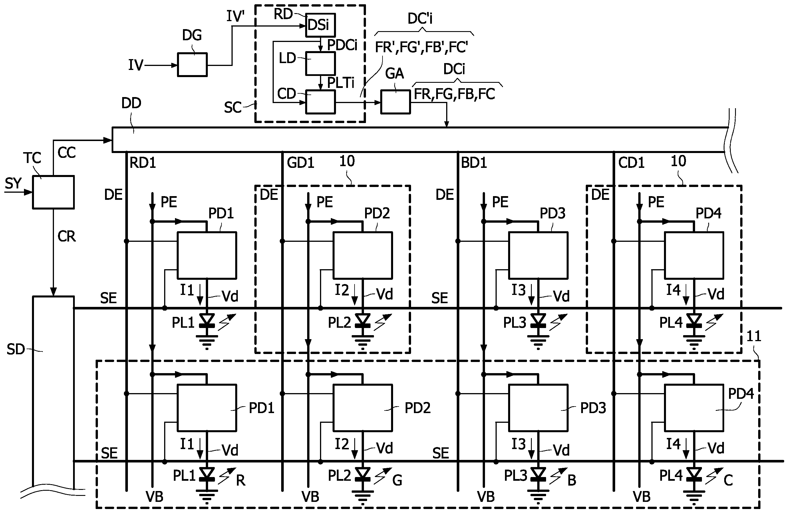
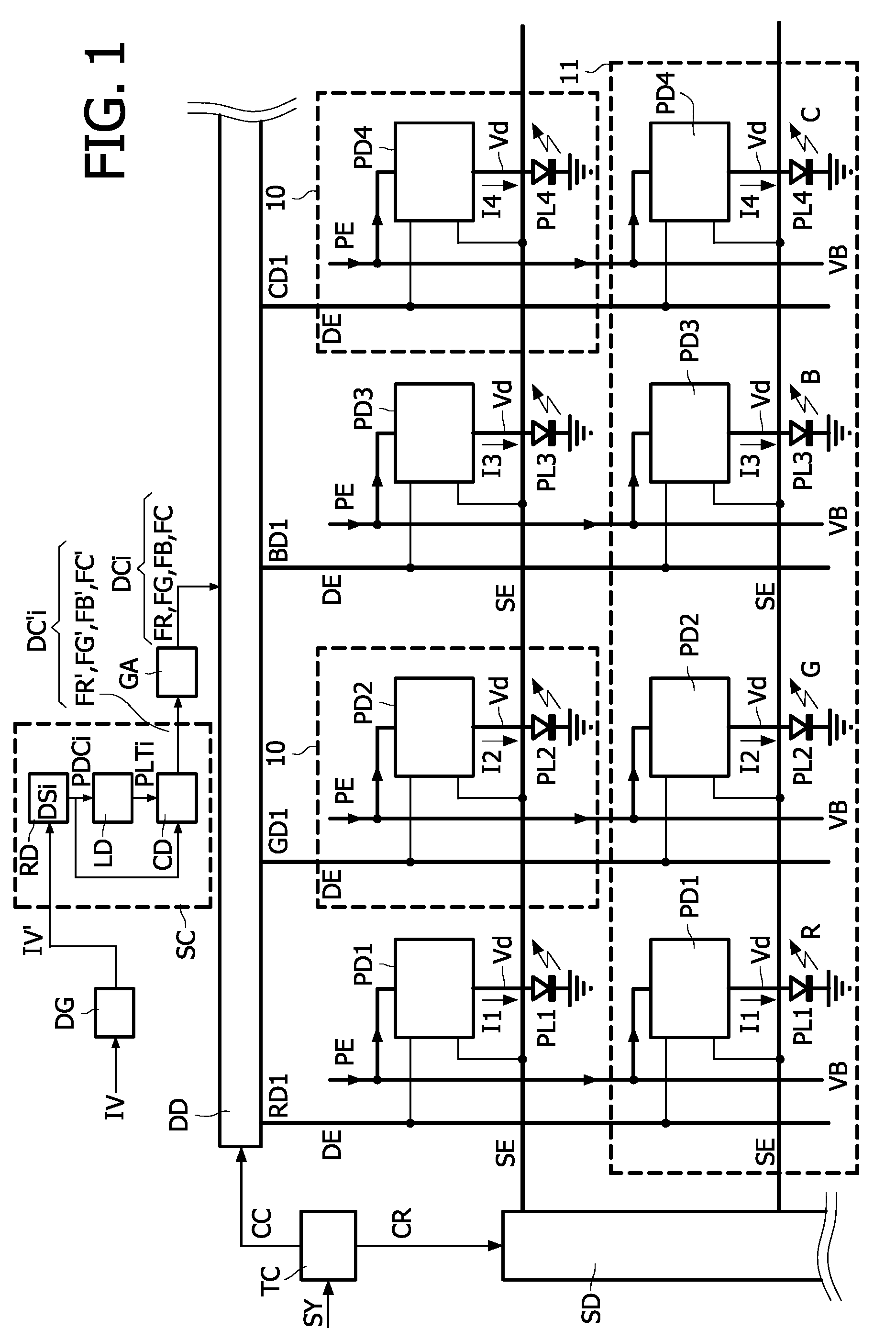
[0031]FIG. 1 shows schematically a display system in accordance with an embodiment of the invention with a display panel which comprises LED's. FIG. 1 shows only eight sub-pixels 10 of a matrix display panel 1. Groups of four sub-pixels 10 form a pixel 11. In a practical implementation, the matrix display panel 1 may have many more pixels 11. It is also possible that the pixels 11 are not arranged in a matrix configuration. The sub-pixels 10 need not be arr...


PUM


Abstract

A method of displaying an input signal (IV) on a full color LED display is discussed wherein the display has pixels (11) comprising at least four LED's (PLi) which respectively emit light with four primary colors. The method comprises converting (SC) the input signal (IV) into drive signals for the at least four LED's (PLi). The converting (SC) comprises: (i) determining (RD) valid ranges (VRi) of at least two of the drive signals (DSi) to obtain a color of the combined light emitted which fits the input signal (IV), (ii) determining (LD) a gradation or lifetime indication (LTi) of the at least two LED's (PLi) for associated ones of the drive signals (DSi) within the valid ranges (VRi), and (iii) determining (CD) a combination (DCi) of values of drive signals (DSi) providing substantially the minimum degradation, or the maximum lifetime, of a combination of the at least two LED's (PLi) based on the degradation or lifetime indications (LTi).

Description

FIELD OF THE INVENTION[0001]The invention relates to a signal converter for a full color LED display, a full color LED display system comprising the signal converter, a display apparatus comprising the full color LED display system, and a method of displaying an input signal on a full color LED display.BACKGROUND OF THE INVENTION[0002]US 2004 / 0178974 A1 discloses a color OLED display system which has an improved performance. The color gamut saturation (further referred to as the saturation) is controlled to reduce the power consumption or to increase the lifetime of at least one of the OLED's. The lifetime of the OLED decreases or the OLED degrades more rapidly, when the current density used to drive the OLED increases. The display system includes a full-color display device which has pixels comprising three or more emissive OLED's which provide three or more primary colors. In one embodiment, the pixels comprise OLED's which emit red, green, blue and white light, respectively. In t...

Claims


Application Information

Patent Timeline
Patent Type & Authority Applications(United States)
IPC IPC(8): G09G3/32H05B44/00
CPCG09G3/3233G09G3/3291G09G2300/0452G09G2360/148G09G2320/0276G09G2320/048G09G2300/0842
Inventor CORDES, CLAUS NICOHOPPENBROUWERS, JURGEN JEAN LOUISBELIK, OLEGBUDZELAAR, FRANCISCO PAULUS MARIAGIRALDO, ANDREAVAN DER VAART, NIJS CORNELISVOGELS, INGRID MARIA LAURENTIA CORNELIA
Owner KONINKLIJKE PHILIPS ELECTRONICS NV
Why Eureka
Try Eureka