Minimizing mismatch during compensation

a phase mismatch and compensation technology, applied in the field of electronic devices, can solve the problems of poor sensitivity in detecting dynamic changes in output signals, poor utilization of output dynamic range, and amplifiers that amplify both

Active Publication Date: 2008-07-03
APPLE INC
View PDF70 Cites 239 Cited by
  • Summary
  • Abstract
  • Description
  • Claims
  • Application Information

AI Technical Summary

Benefits of technology

[0009]In a further embodiment, both the compensation signals and the drive signals applied to the drive electrodes of a touch surface panel are generated to be sinusoidal waveforms so as to minimize the effects of any phase mismatches between the resulting sinusoidal output signals from each pixel and the corresponding sinusoidal waveforms used to compensate the output signals.

Problems solved by technology

The problem with this configuration is that the amplifier amplifies both the dynamic signal of interest as well as the undesired static or offset portion.
Additionally, by compensating the output signal after it has been amplified, conventional compensation methods provide poor utilization of the output dynamic range of the amplifier, which results in poor sensitivity in detecting dynamic changes in the output signal.
The large feedback capacitors, however, consume a significant amount of integrated circuit (IC) chip “real estate” and hence, add significant costs and size requirements to the IC chips.
Therefore, a constant compensation signal does not provide optimized compensation to every pixel output.
Additionally, the touch surface electrodes can impose a phase delay on the drive or stimulus waveform passing through it.
For higher resistance values, a significant time (phase) delay in the propagation of the stimulus voltage through the panel may occur.
This phase delay causes the output signals from the panel to be delayed before entering an amplifier, for example.

Method used


Image

  • Minimizing mismatch during compensation
  • Minimizing mismatch during compensation
  • Minimizing mismatch during compensation

Examples


Embodiment Construction

[0036]In the following description of preferred embodiments, reference is made to the accompanying drawings which form a part hereof, and in which it is shown by way of illustration specific embodiments in which the invention may be practiced. It is to be understood that other embodiments may be utilized and structural changes may be made without departing from the scope of the present invention. Furthermore, although embodiments of the present invention are described herein in terms of devices and applications compatible with computer systems and devices manufactured by Apple Computer, Inc. of Cupertino, Calif., such embodiments are illustrative only and should not be considered limiting in any respect.

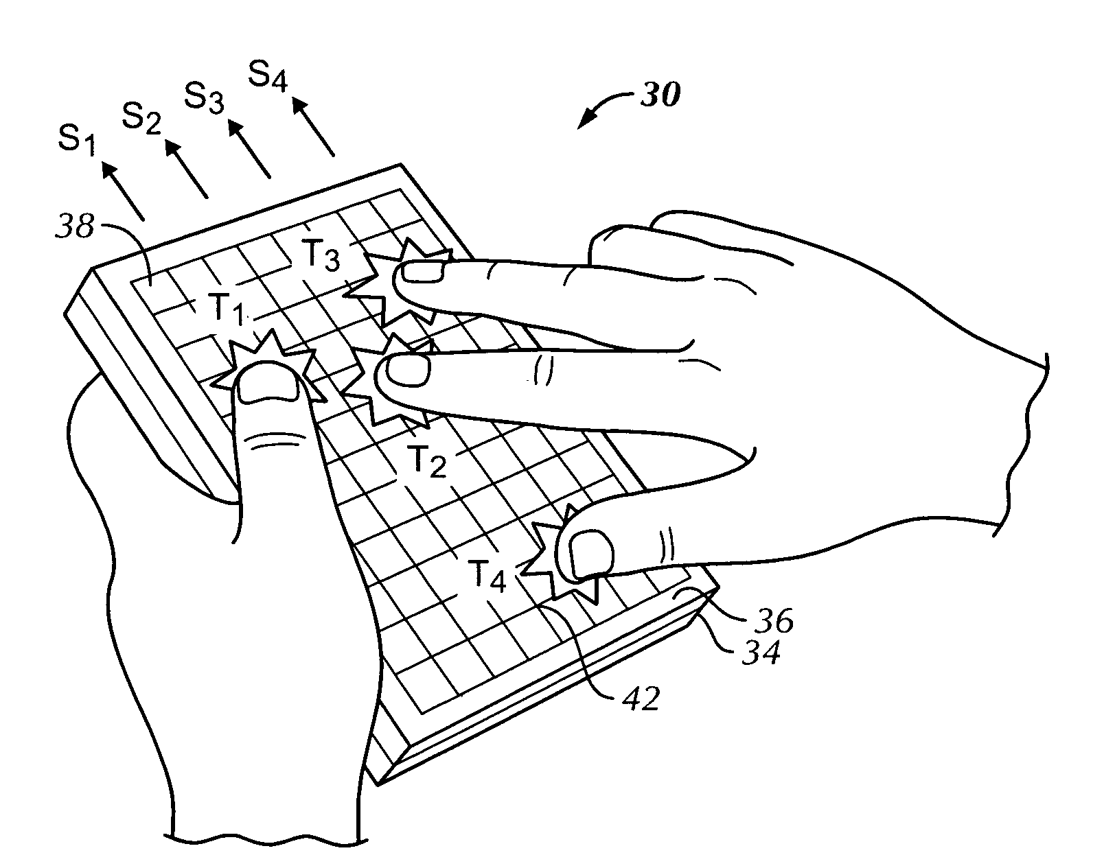
[0037]FIG. 1 is a perspective view of a touch screen display arrangement 30, which includes a display 34 and a transparent touch screen 36 positioned in front of display 34. Display 34 may be configured to display a graphical user interface (GUI) including perhaps a pointer or cursor...


PUM


Abstract

A method and apparatus for minimizing mismatch effects between a compensation signal and an output signal generated by a touch surface device is disclosed. In one embodiment the apparatus includes a touch-sensitive panel having a sense node for providing an output signal indicative of a touch or no-touch condition on the panel; a drive circuit for generating a sinusoidal drive signal provided to the sense node of the touch-sensitive panel; at least one non-touch-sensitive node within the touch-sensitive panel, for generating a sinusoidal compensation signal, wherein the sinusoidal compensation signal is summed with the output signal to provide a sinusoidal compensated output signal; and a sensing circuit for receiving the sinusoidal compensated output signal.

Description

FIELD OF THE INVENTION[0001]This disclosure relates generally to electronic devices (e.g., a touch screen) capable of generating a dynamic output signal, and more particularly, to a method and system of compensating for undesired portions (e.g., a static portion) of the output signal.BACKGROUND OF THE INVENTION[0002]One example of an electronic device that generates dynamic output signals is a user input device for performing operations in a computer system. Such input devices generate output signals based on user operation of the device or user data or commands entered into the device. The operations generally correspond to moving a cursor and / or making selections on a display screen. By way of example, the input devices may include buttons or keys, mice, trackballs, touch pads, joy sticks, touch screens and the like. Touch pads and touch screens (collectively “touch surfaces”) are becoming increasingly popular because of their ease and versatility of operation as well as to their ...

Claims


Application Information

Patent Timeline
Patent Type & Authority Applications(United States)
IPC IPC(8): G06F3/041
CPCG06F3/0418
Inventor HOTELLING, STEVE PORTERLAND, BRIAN RICHARDS
Owner APPLE INC
Why Eureka
Try Eureka