Method and device for multi-grayscale display

a multi-grayscale display and display method technology, applied in the field of multi-grayscale display devices, can solve the problems of deterioration of image quality, reducing multi-grayscale expressive power, and reducing image quality, so as to reduce power consumption, improve screen brightness, and reduce multi-grayscale expressive power.

Inactive Publication Date: 2008-07-03
FUJITSU HITACHI PLASMA DISPLAY LTD
View PDF5 Cites 3 Cited by
  • Summary
  • Abstract
  • Description
  • Claims
  • Application Information

AI Technical Summary

Benefits of technology

[0008]In the system in which power consumption is reduced and screen brightness is improved in the conventional technique, even when APL of the image is detected, there exist various distribution situations of data level (signal value) depending on the image and thus the multi-grayscale expressive power often reduces. For example, even the case where the APL of image is at the same 50%, there are a case of an image whose levels are all close to 50%, and a case of an image in which the number of pixels with levels close to 0% is 50% and the number of pixels with levels close to 100% is 50%. In the latter case, when the number (N) of subfields is reduced by a field driving control according to the APL (especially when the subfields of a small weight are eliminated), the number of grayscale levels (the number of steps) is reduced, thereby reducing the expressive power of low grayscale.

Problems solved by technology

In the system in which power consumption is reduced and screen brightness is improved in the conventional technique, even when APL of the image is detected, there exist various distribution situations of data level (signal value) depending on the image and thus the multi-grayscale expressive power often reduces.
However, in this case, since Off-subfields are increased, the pseudo contour noise is strengthened, and thus it invites a deterioration of the image quality.
This causes a user to recognize a switching shock, and by that much, the image quality is deteriorated.

Method used


Image

  • Method and device for multi-grayscale display
  • Method and device for multi-grayscale display
  • Method and device for multi-grayscale display

Examples


second embodiment

[0106]Next, by using FIG. 12, a second embodiment of the present invention will be described. In the second embodiment, in addition to the configuration of the first embodiment in which the SF conversion only for reducing the number (N) of SFs is used, further, an SF conversion in which the rest time by the rest SF portion is distributed to other SFs so as to increase luminance is selected and used. While the configuration of the second embodiment is basically the same as that of the first embodiment, weighting in the conversions (SFD2 and SFD3) by the SF conversion unit 23 is kept as it is, but the number of sustain pulses are different. The number of sustain pulses is calculated by the driving sequence generating unit 9 based on the signal SEL.

[0107]2)>

[0108]In FIG. 12, a second configuration of the driving control of a plurality (the number of SF: N) of SFs of one field in the second embodiment is shown. As respective driving sequences corresponding to SFD1, SFD2, and SFD3, Dr10,...

third embodiment

[0115]Next, with reference to FIG. 13 to FIG. 16, a third embodiment of the present invention will be described. In the third embodiment, in addition to the switching of a plurality of SF conversions like the first and second embodiments, when a position of the temporal weighted emission center changes by the switching of an SF conversion, a transient conversion (driving sequence) to gently change the position of the weighted emission center during that period is further provided, thereby performing the switching step by step.

[0116]3-1)>

[0117]In FIG. 13, a first configuration of a driving control of the third embodiment will be described. Note that, subsequent to the present embodiment, an example is shown in which the switching is made on the configuration (SFD2) in which the number (N) of SFs is 9. This is similar to the configuration (SFD3) in which the number (N) of SFs is 8.

[0118]In FIG. 13, a case of switching from Dr10 to Dr9Z is shown. Between Dr10 and Dr9Z, Dr9 and Dr9S are...

fourth embodiment

[0131]Next, with reference to FIG. 1, FIG. 3, and FIG. 17, a fourth embodiment will be described. In the fourth embodiment, in addition to the same configuration as that of the first embodiment and the like, further, as a control condition, APL is used in addition to the number (p) of pixels of low grayscales so that a control of SF conversion switching is performed.

[0132]4)—APL Detection>

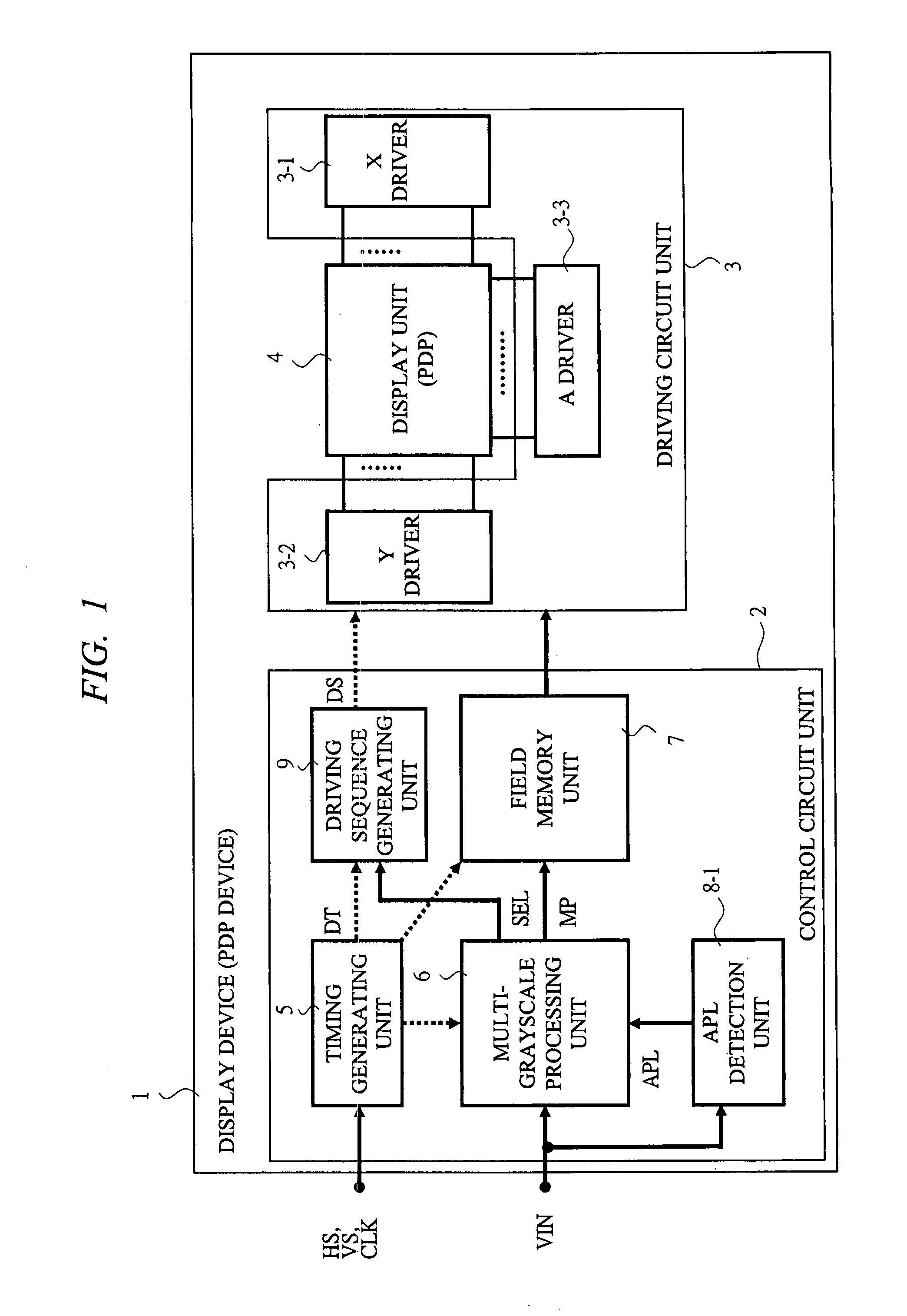
[0133]In FIG. 1 described above, as the configuration of the display device 1, a control circuit unit 2 is provided with an APL detection unit 8-1. The APL detection unit 8-1 gets a picture signal (VIN) inputted, and detects an average luminance level (APL: Average Picture Level) per image corresponding to one field as the picture content and outputs its signal (APL) to the multi-grayscale processing unit 6.

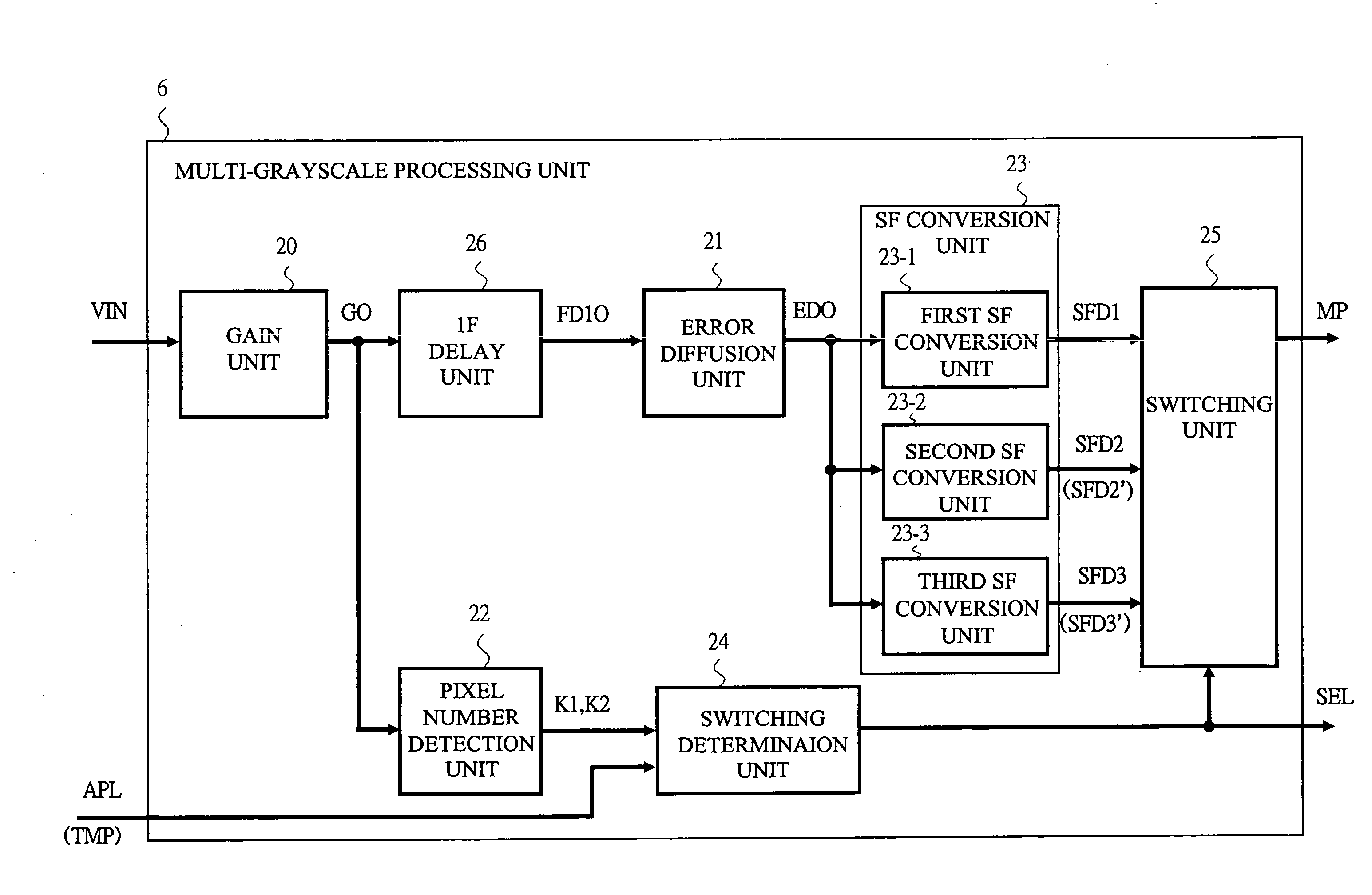
[0134]Further, in FIG. 3 described above, in the multi-grayscale processing unit 6 of the present display device 1, the inputs of the switching determination unit 24 are three signals of K1, K2,...


PUM


Abstract

A multi-grayscale display device to appropriately control brightness of a display (screen) and power according to the content of a picture while preventing deterioration of image quality of a picture, so that both of these performances are improved. In a multi-grayscale processing unit of the display device (PDP device), in a subfield (SF) driving control, the number of pixels of low grayscales in an image of an input picture signal is detected and determined by an image number detection unit, and accordingly, a selection signal to switch one from outputs of a plural types of SF conversions of an SF conversion unit is determined and outputted by a switching unit. In the control, an SF conversion in which the number of rest SF becomes large as the number of pixels of low grayscales becomes small selected.

Description

CROSS-REFERENCE TO RELATED APPLICATION[0001]The present application claims priority from Japanese Patent Application No. JP 2006-326874 filed on Dec. 4, 2006, the content of which is hereby incorporated by reference into this application.BACKGROUND OF THE INVENTION[0002]The present invention relates to a technique for a multi-grayscale display device (digital display device) for displaying a multi-grayscale picture (moving image) on a display panel. More particularly, the present invention relates to a technique for controlling a luminance of picture and power in a display driving control using a subfield method in a display device (plasma display device: PDP device) and the like comprising a plasma display panel (PDP).[0003]In recent years, a demand for thin-type display devices has been growing along with the display devices becoming larger, and so various types of thin-type display devices are provided. For example, a Matrix Panel that displays with digital signals as they are, i...

Claims


Application Information

Patent Timeline
Patent Type & Authority Applications(United States)
IPC IPC(8): G09G5/10G09G3/288G09G3/20G09G3/28G09G3/291G09G3/292G09G3/293G09G3/294G09G3/298H04N5/66
CPCG09G2360/16G09G3/2059G09G2330/021G09G2320/041G09G2310/065G09G3/291G09G3/296G09G5/02
Inventor CHIAKI, YUTAKAITOKAWA, NAOKITAKADA, YOSHIAKI
Owner FUJITSU HITACHI PLASMA DISPLAY LTD
Why Eureka
Try Eureka