
Weatherization imaging systems and methods

a weatherization imaging and imaging system technology, applied in the field of weatherization imaging systems and methods, can solve problems such as damage to buildings or structures, limited methods, and prone to considerable errors

Active Publication Date: 2008-07-03
JOHNS MANVILLE CORP
View PDF9 Cites 32 Cited by
  • Summary
  • Abstract
  • Description
  • Claims
  • Application Information

AI Technical Summary

Benefits of technology

[0006]Advantageously, embodiments of the present invention provide imaging techniques that evaluate the effectiveness of weatherization, comfortization, or other performance measures that are implemented in a building or structure. For example, before and after thermal images can be provided to homeowners to illustrate resultant heat flow reductions. Relatedly, images can be used as part of a computer program to map out cavities for drilling and determine how much insulation should be added to each cavity. In some embodiments, images can provide a map to show where air sealing is needed or desired. Before and after ima

Problems solved by technology

Although drill and fill techniques and other weatherization and comfortization procedures provide many benefits to a building or home, such methods may have heretofore been limited due to the lack of effective solutions for accurately gauging the adequacy of the procedure.
For example, because the drill and fill technique is often a “blind” procedure where the installer cannot see the material being placed within the interior construction cavity, it is typically difficult for the contractor, the homeowner, or both, to know that the cavity has been adequately filled, that no voids or compressions are present, and that the correct insulation density exists in a uniform manner throughout one or more cavities, to provide a desired level of thermal and acoustic performance.
However, such methods are often prone to considerable error, and some can even cause damage to the building or structure.

Method used


Image

  • Weatherization imaging systems and methods
  • Weatherization imaging systems and methods
  • Weatherization imaging systems and methods

Examples


Embodiment Construction

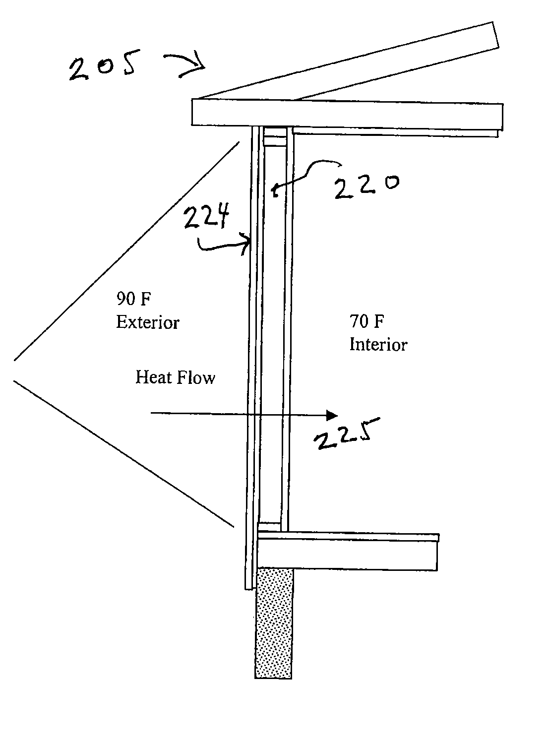
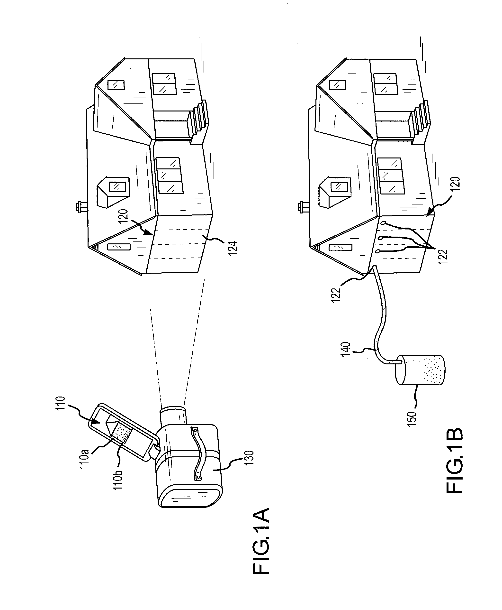
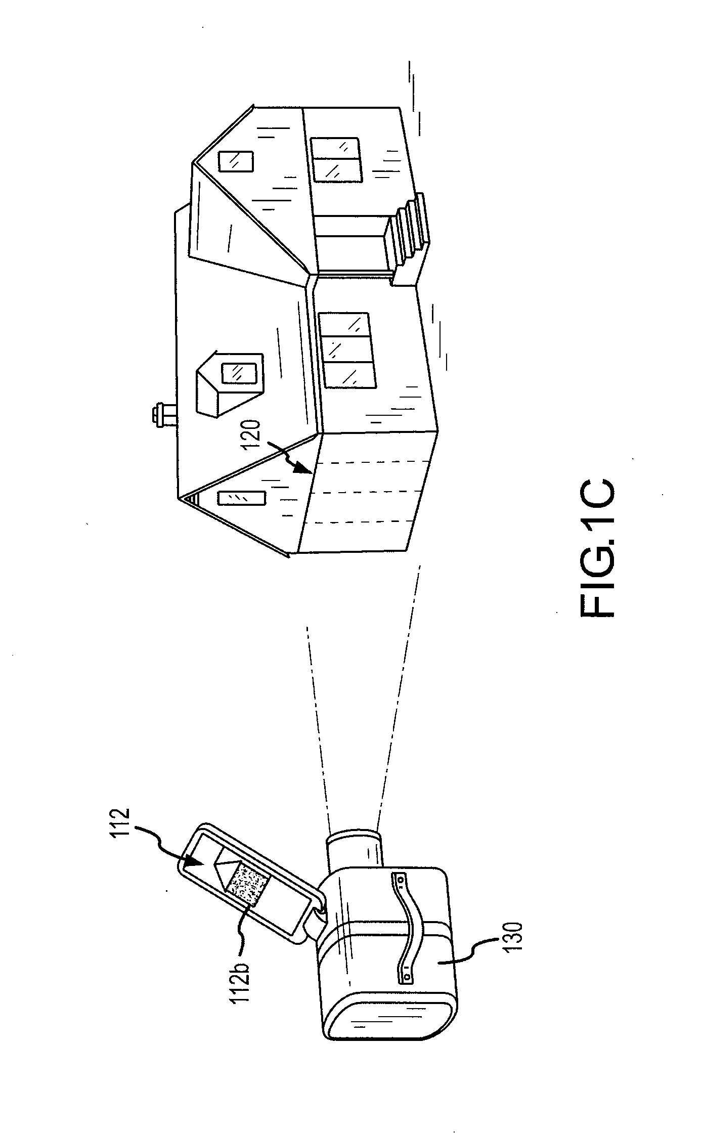
[0014]Embodiments of the present invention provide imaging techniques to accurately map areas of a building both before and after implementing performance measures such as weatherization or comfortization installments. Often, such imaging involves thermal or infrared technology. In the case of drill and fill insulation procedures, maps can be used to evaluate whether the desired cavities were filled, to determine if any unwanted voids or compressions are present, and to check that the desired level of thermal performance was achieved.

[0015]A portable thermal imaging camera can be used to capture the heat loss (winter) or heat gain (summer) signatures on one or more sections of a building structure or construction. This information can be downloaded to a computer containing mapping software which can be used to develop a detailed structural map of the building along with the calculated amount of insulation required in each cavity of the building. The map can also show installers wher...


PUM


Abstract

Methods and systems for evaluating a performance installment in a building construction include preparing a first image of the building construction, implementing the performance installment in the building construction, preparing a second image of the building construction subsequent to or during implementation of the performance installment, and evaluating the performance installment based on a comparison between the first image and the second image. Performance installments include weatherization measures such as the application of thermal insulation and air-sealing. Related methods and systems for calculating a performance plan for a building construction include transmitting analysis information to a processor, and determining the performance plan based on the analysis information. The analysis information may include a thermal signature, an airflow signature, an acoustic signature, or a vibrational signature.

Description

BACKGROUND OF THE INVENTION[0001]Embodiments of the present invention relate to systems and methods for evaluating weatherization techniques, and in particular to approaches for determining the quality and effectiveness of building insulation measures.[0002]A variety of approaches can be used to weatherize or comfortize a building or structure. For example, it is possible to add insulation to wall, ceiling, and floor constructions to achieve a desired level of thermal, acoustic, or vibrational performance. Such insulation measures, which include drill and fill techniques, have long been employed by insulation contractors, re-modelers, and do-it-yourselfers. Drill and fill techniques typically involve drilling holes or cutting access slots into an un-insulated, under-insulated, or semi-insulated cavity of a given structure and then filling the cavity with pneumatically applied insulation or pressurized foam.[0003]Although drill and fill techniques and other weatherization and comfort...

Claims


Application Information

Patent Timeline
IPC IPC(8): G06K9/00
CPCG01N25/72
Inventor FELLINGER, THOMAS J.
Owner JOHNS MANVILLE CORP
Learn More