
Channel scan logic

Active Publication Date: 2008-07-03
ALLLE INC
View PDF49 Cites 208 Cited by
  • Summary
  • Abstract
  • Description
  • Claims
  • Application Information

AI Technical Summary

Benefits of technology

[0006]Use of channel scan logic to implement one or more of the above described functions can permit a processor to perform other tasks or power down. For example, in an auto-scan mode, channel logic performs periodic scans of a sensor panel with the sensor

Problems solved by technology

One limitation of many conventional touch panel technologies is that they are only capable of reporting a single point or touch event, even when multiple objects come into contact with the sensing surface.
That is, they lack the ability to track multiple points of contact at the same time.
Moreover, detecting and processing of events detected on a sensor panel can take a significant amount of processing power.
The significant amount of processing can make a processor too busy to perform other functions and can slow down devices using a sensor panel.
Additionally, processors typically consume a significant amount of power during operation, which can be particularly problematic when a sensor panel is used in conjunction with a hand held device, as many hand-held devices have a limited power supply.

Method used


Image

  • Channel scan logic
  • Channel scan logic
  • Channel scan logic

Examples


Embodiment Construction

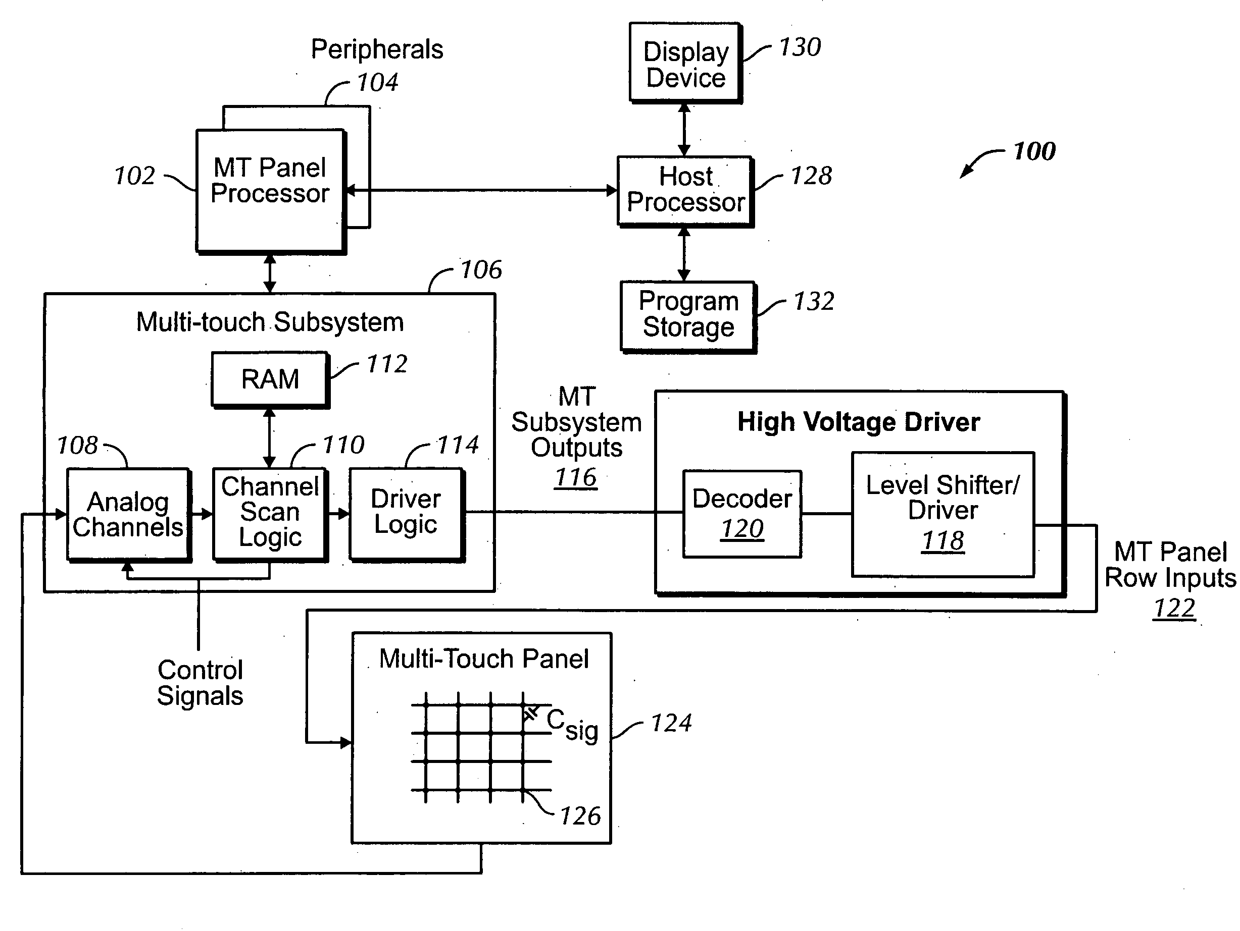
[0022]In the following description of preferred embodiments, reference is made to the accompanying drawings which form a part hereof, and in which it is shown by way of illustration specific embodiments in which the invention may be practiced. It is to be understood that other embodiments may be used and structural changes may be made without departing from the scope of the preferred embodiments of the present invention.

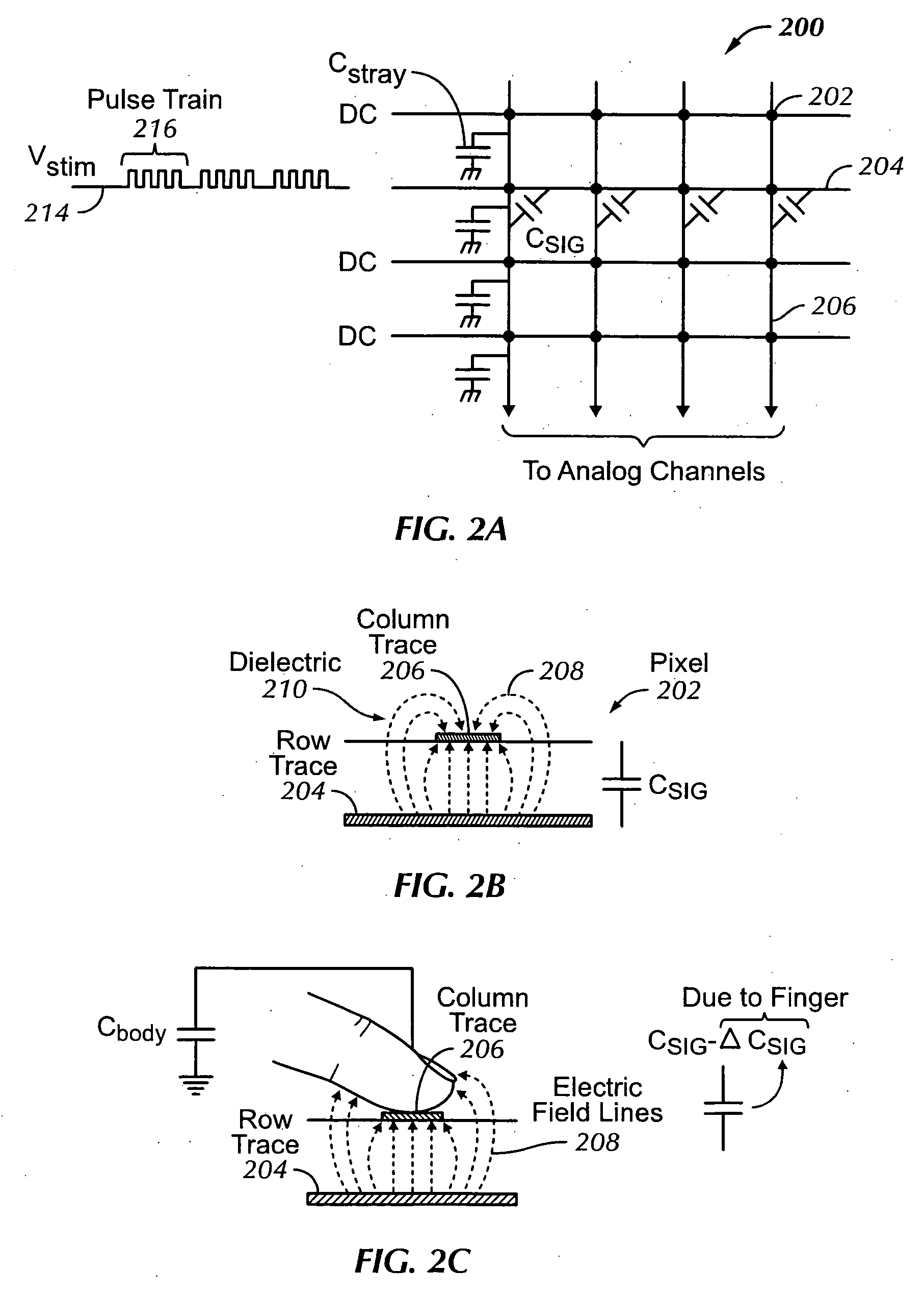
[0023]A plurality of touch sensors in a multi-touch panel can enable a computing system to sense multi-touch events (the touching of fingers or other objects upon a touch-sensitive surface at distinct locations at about the same time) and perform additional functions not previously available with touch sensor devices.

[0024]Although some embodiments may be described herein in terms of capacitive touch sensors in a multi-touch panel, it should be understood that embodiments of the invention are not so limited, but are generally applicable to the use of any type of mult...


PUM


Abstract

A device that can autonomously scan a sensor panel is disclosed. Autonomous scanning can be performed by implementing channel scan logic. In one embodiment, channel scan logic carries out many of the functions that a processor would normally undertake, including generating timing sequences and obtaining result data; comparing scan result data against a threshold value (e.g., in an auto-scan mode); generating row count; selecting one or more scanning frequency bands; power management control; and performing an auto-scan routine in a low power mode.

Description

FIELD OF THE INVENTION[0001]This invention relates generally to sensor panels used as input devices for computing systems, and more particularly, using logic circuitry to autonomously detect and process events (e.g., a touching or a near touching of an object) on a sensor panel.BACKGROUND OF THE INVENTION[0002]Many types of input devices are presently available for performing operations in a computing system, such as buttons or keys, mice, trackballs, touch panels, joysticks, touch screens and the like. Touch screens, in particular, are becoming increasingly popular because of their ease and versatility of operation as well as their declining price. Touch screens may include a touch panel, which may be a clear panel with a touch-sensitive surface. The touch panel may be positioned in front of a display screen so that the touch-sensitive surface covers the viewable area of the display screen. Touch screens may allow a user to make selections and move a cursor by simply touching the d...

Claims


Application Information

Patent Timeline
IPC IPC(8): G06F11/22
CPCG06F3/03545G06F3/041G06F3/044G06F3/0446G06F3/04166G06F3/0445G06F3/0416G06F1/3262G06F2203/04104
Inventor VU, MINH-DIEU THIWILSON, THOMAS JAMESKRAH, CHRISTOPH HORST
Owner ALLLE INC
Learn More