Snowthrower deflector control

a technology for deflectors and snowthrowers, applied in the field of snowthrowers, can solve the problems of complex and costly approach, difficult for some operators to do, and stiffness of deflectors, and achieve the approach disclosed in the 333 patent, which is the use of remote control handles and mechanical connecting links, and is more complex and costly

Active Publication Date: 2008-07-10
TORO CO THE
View PDF13 Cites 5 Cited by
  • Summary
  • Abstract
  • Description
  • Claims
  • Application Information

AI Technical Summary

Benefits of technology

[0007]One aspect of this invention relates to a snowthrower of the type having a chute rotatable about a substantially vertical axis for directing a snow stream, a deflector carried on the chute with the deflector being pivotal relative to the chute for adjusting the trajectory of the snow stream, and a control on the snowthrower for operating the deflector. The improvement relates to the control which comprises a handle on the deflector to allow an operator to grip the handle to pivot the deflector. A movable latch is

Problems solved by technology

Thus, the deflector often feels very stiff when the operator grabs the handle to adjust the deflector.
This can be difficult for some operators to do.
However, the approach disclosed in the 333 patent, namely

Method used


Image

  • Snowthrower deflector control
  • Snowthrower deflector control
  • Snowthrower deflector control

Examples


Embodiment Construction

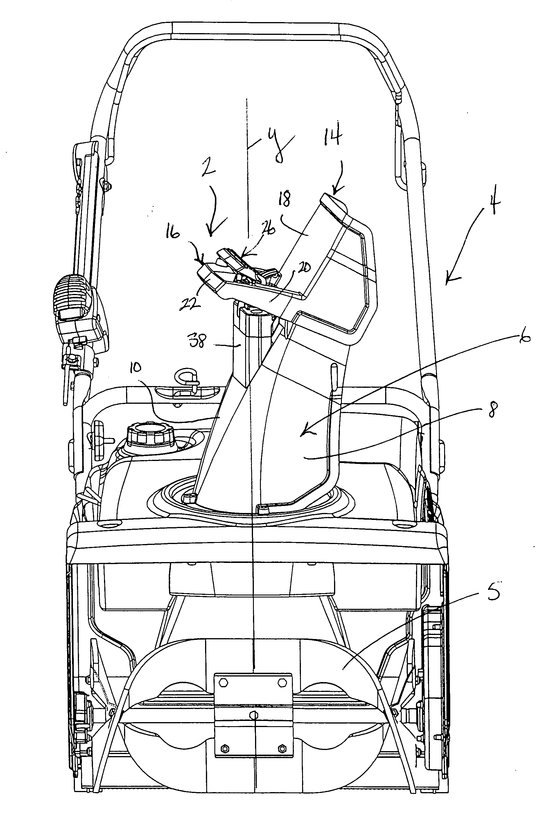
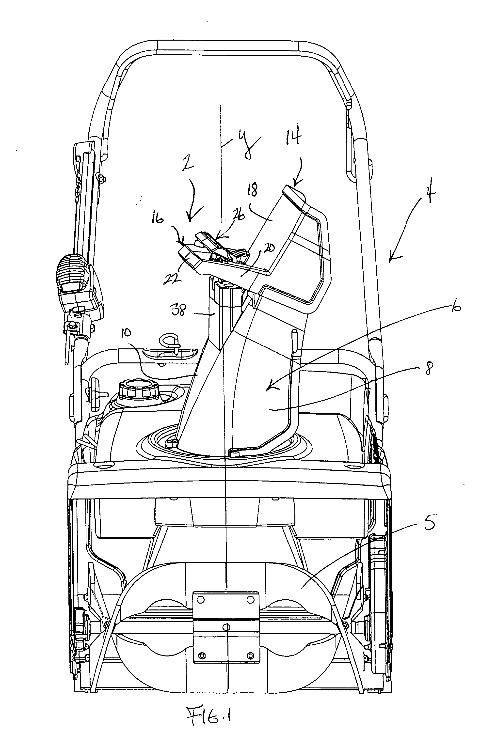
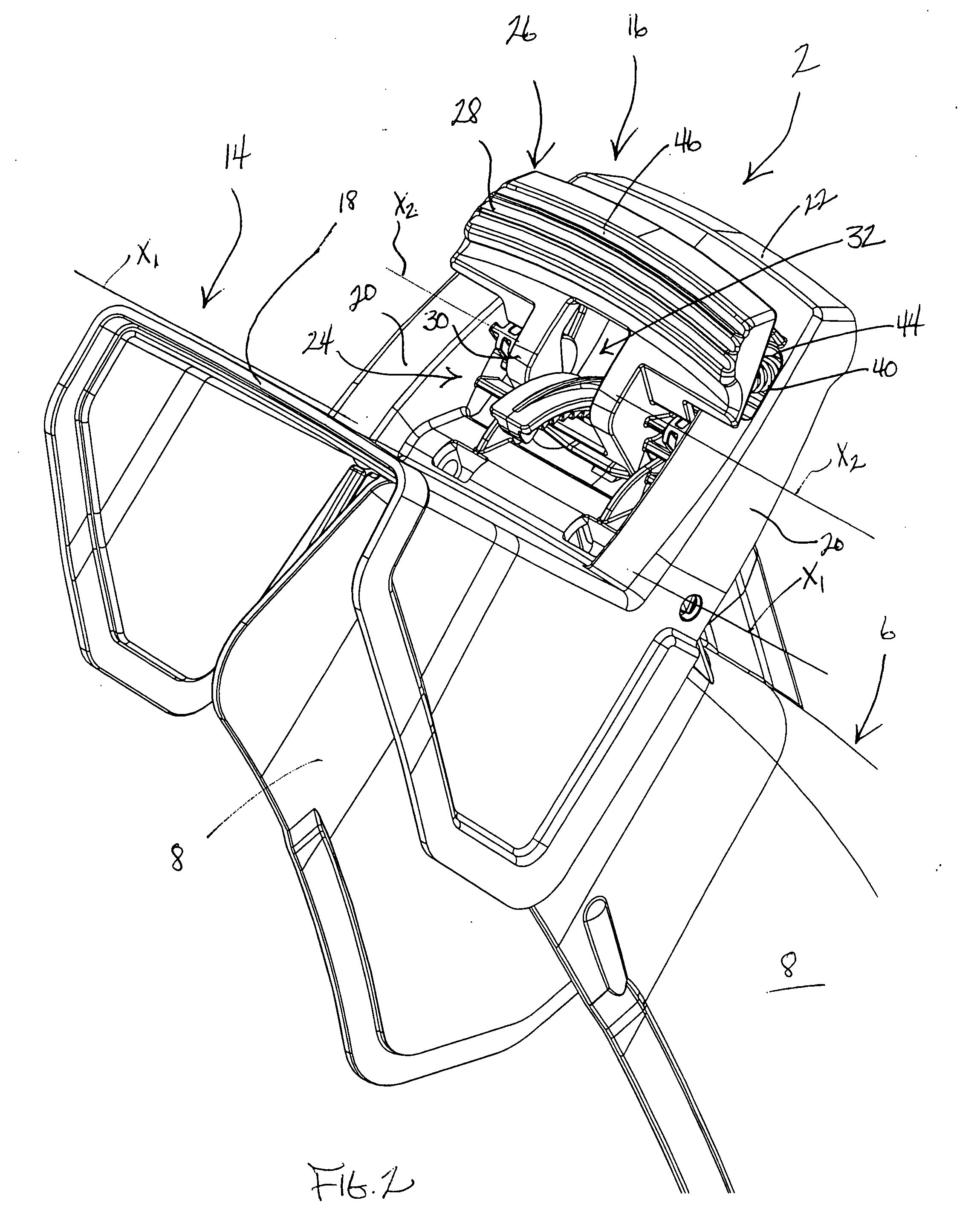
[0016]One embodiment of a snowthrower chute control according to this invention is illustrated generally as 2 in FIGS. 1-8. A typical snowthrower of the type with which control 2 may be used is illustrated generally as 4. Snowthrower 4 may be any snowthrower incorporating suitable snow removal components for gathering snow from the ground and for throwing the gathered snow in a snow stream away from the snowthrower. Thus, snowthrower 4 may be either a single stage snowthrower having a single snow gathering and throwing impeller 5. Alternatively, snowthrower 4 could be a two stage snowthrower having an auger for gathering snow as well as an impeller for throwing the snow gathered by the auger.

[0017]Snowthrower 4 is also of the type having a generally upright or vertically extending chute 6 through which the snow stream is thrown. As shown in FIGS. 1 and 2, chute 6 is generally U-shaped having spaced, parallel side walls 8 connected together by a back wall 10. The bottom or base of ch...


PUM


Abstract

A U-shaped handle is physically attached to the back of a deflector atop a snow directing chute on a snowthrower. The deflector pivots atop the chute to adjust the trajectory of a stream of snow being thrown by the snowthrower. The handle is gripped and moved up and down to effect a pivotal adjustment of the deflector. A pivotal latch is carried on the handle which latch protrudes into the open interior hand grip space of the handle. The latch is spring biased so that a detent on the latch engages with a toothed rack with the interengagement between the detent and the rack holding the deflector in an adjusted position. When the operator grips the handle and squeezes the fingers of the gripping hand closed, the latch is pivoted to remove the detent from the rack and thereby permit pivotal adjustment of the deflector.

Description

TECHNICAL FIELD [0001]This invention relates to snowthrowers having a rotatable chute for adjusting the direction of a snow stream thrown by the snowthrower. More particularly, this invention relates to a pivotal deflector atop the chute for further adjusting the angle of trajectory of the snow stream.BACKGROUND OF THE INVENTION [0002]Snowthrowers are known having upright chutes through which a snow stream is thrown. Such chutes are rotatable about a vertical axis to vary the direction of the snow stream being thrown through the chute relative to the snowthrower. If the chute points forwardly, then the snow stream will be thrown forwardly in front of the snowthrower. However, if the chute is rotated to one side or the other, then the snow stream will be thrown laterally to the side to which the chute is directed. The chute can be left in intermediate rotated positions where the snow stream is thrown both partially forwardly and partially to one side.[0003]Most snowthrowers having ro...

Claims


Application Information

Patent Timeline
IPC IPC(8): E01H5/09
CPCE01H5/045Y10T292/57
Inventor WHITE, DONALD M.
Owner TORO CO THE
Why Eureka
Try Eureka