Bicycle training wheel assembly

Inactive Publication Date: 2008-07-10
BELL WILLIAM MARK
View PDF14 Cites 13 Cited by
  • Summary
  • Abstract
  • Description
  • Claims
  • Application Information

AI Technical Summary

Benefits of technology

[0016]A damper section connected beneath the intermediate section of the compression fitting provides additional shock resistance. The damper section comprises a rigid, tubular sleeve attached under the intermediate section, that coaxially receives a slidable, tubular cap. A resilient grommet is coaxially confined between the sleeve and the adjustable cap. An elongated through bolt coaxially penetrating all three aligned sections of the compression fitting. The cap is telescopically displaceable relative to the sleeve, and the two are compressed by the through bolt to enable variable damping resistance for controlling the training wheels and their supporting legs.
[0031]Yet another object of the invention is to provide a training wheel assembly whose wheels are able to deflect and compensate as the bicycle leans or tilts as it is steered. A feature enabled by my structural combination is that by leaning the bicycle, a rider is allowed to turn more sharply, thereby avoiding obstacles.

Problems solved by technology

In my opinion known prior art devices do not perform safely.
Many known devices that are not well built and properly designed, are unsafe.
They do not stay in proper adjustment, they break easily, and bend or become deformed, even with relatively minor shocks or slight misuse.
Many prior art training wheel devices are difficult to install, adjust and service.
Many prior art devices use a spring to mount their frame tubes, which often causes excessive bouncing, which contributes to the loss of control.
There are numerous problems with prior art designs such as those referenced above.
Many are difficult to install or align.
While inherent flexibility of the wheel mounts is desirable to promote stability, such designs may tend to loosen the mounting brackets or hardware used to mount them.

Method used


Image

  • Bicycle training wheel assembly
  • Bicycle training wheel assembly
  • Bicycle training wheel assembly

Examples


Embodiment Construction

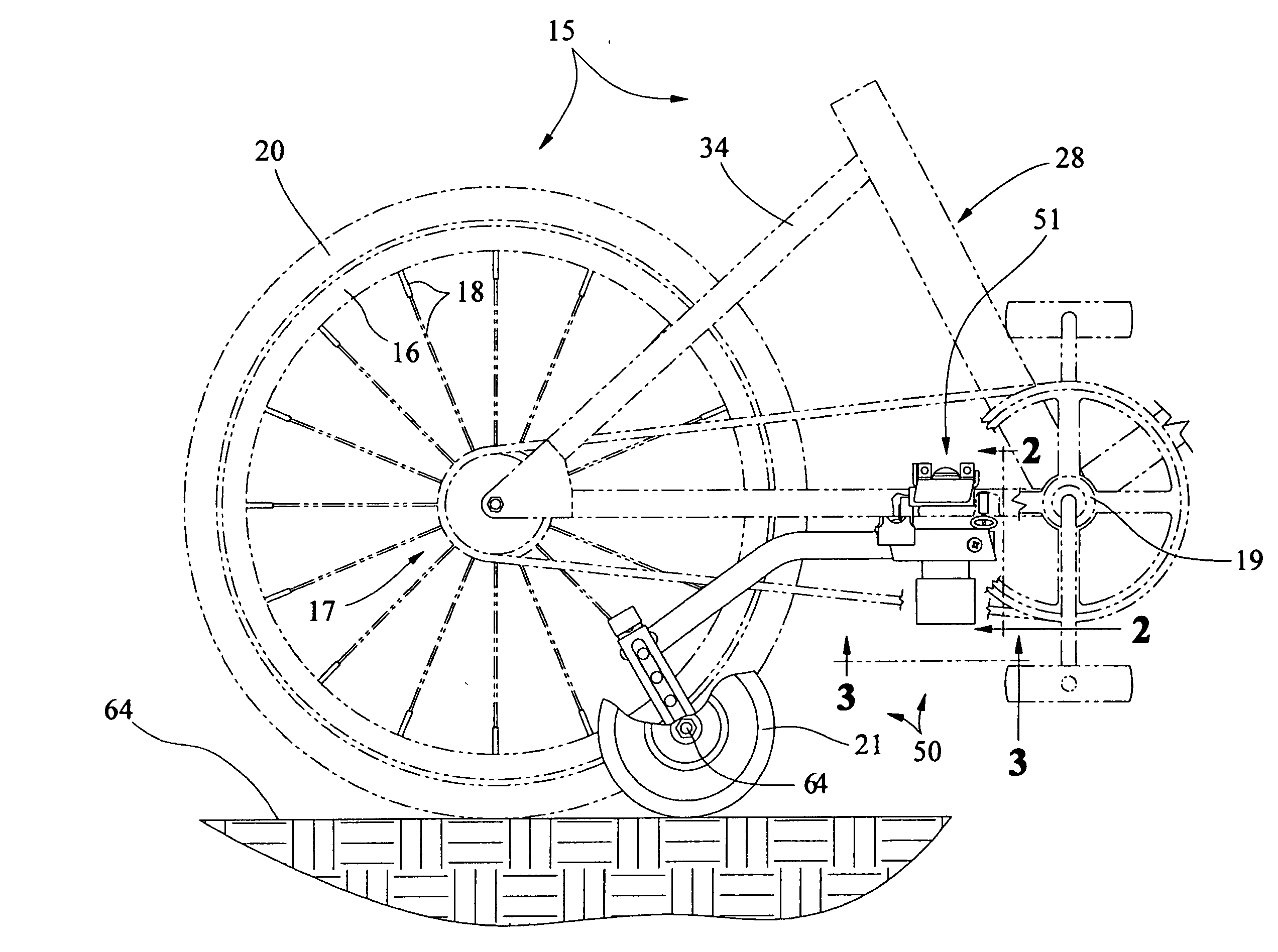
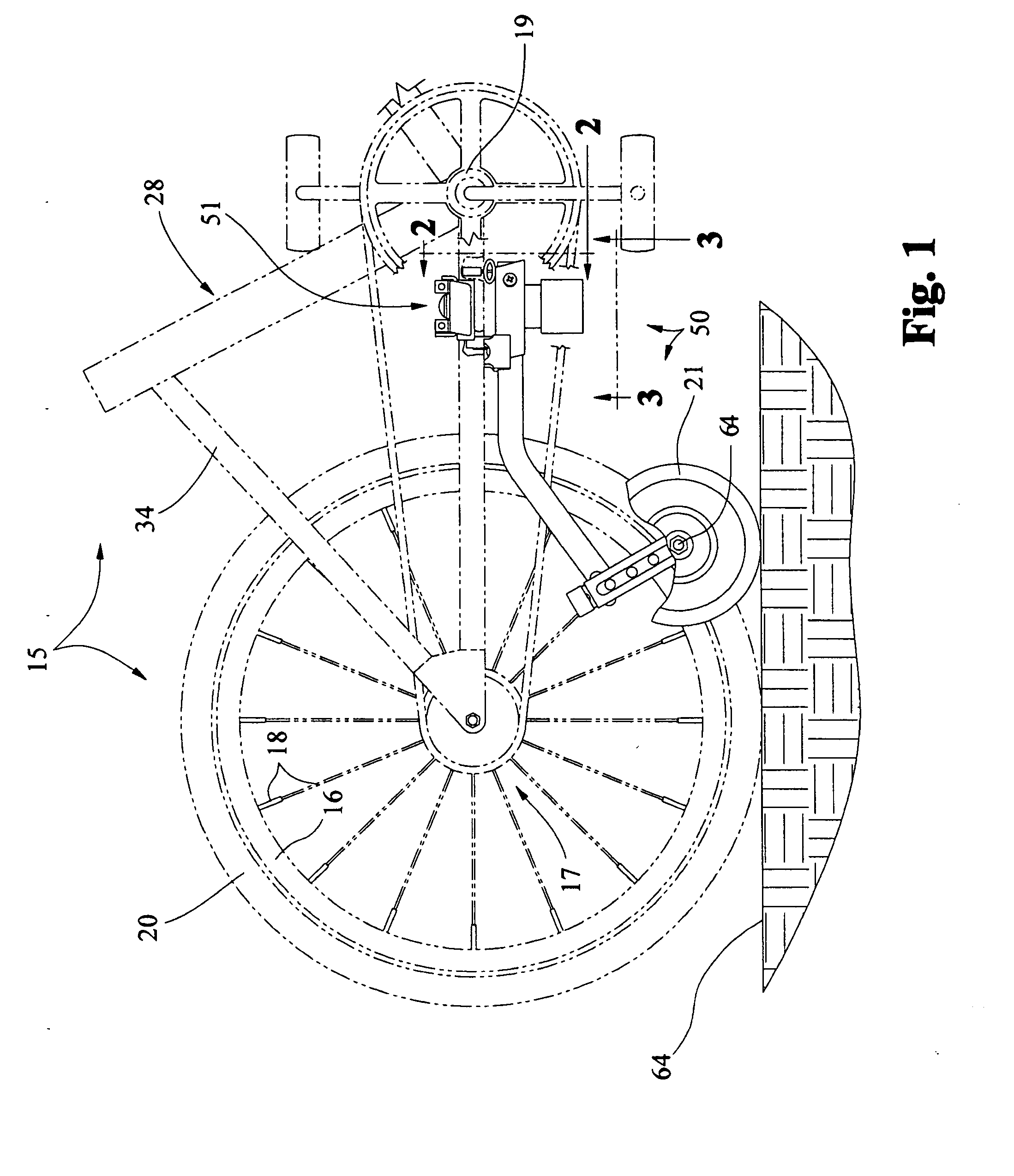
[0053]Initially referring to FIGS. 1-4, 7 and 8, a conventional bicycle upon which the invention is to be deployed and used is designated generally by the reference numeral 15. As only the rear section of the bicycle 15 is important for the disclosure, front parts of the conventional bicycle 15 have been omitted for brevity. The bicycle rear supports a conventional rear wheel assembly 17 that is to be stabilized by the training wheel assembly discussed hereinafter as the bike rolls over a variety of surfaces, such as the ideal flat surface 32 (FIG. 1).

[0054]A conventional rear bicycle wheel 20 is rotatably supported by axle 70 (FIG. 4) that penetrates the rear of both rearwardly extending, horizontally disposed bicycle side frame tubes 27 and 31 (i.e., FIGS. 3, 5) to secure conventional drive sprocket 26. Conventional radially spaced apart spokes 18 extend between wheel rim 16 and the sprocket 26. Bicycle frame tubes 27, 31 extend to a conventional transverse crank sleeve 19 to whic...


PUM


Abstract

A training wheel assembly for standard bicycles comprises training wheels connected by resilient legs to a dynamic compression fitting. The wheels project generally rearwardly and outwardly apart from the bicycle rear. Adjustable mounting brackets enable wheel height to be varied. The dynamic compression fitting comprises an adjustable flange section mounted to the bicycle frame within the standard trapezoidal void to the rear of the crank sleeve. A pair of yoke segments can be slidably adjusted to accommodate varying dimensions. An intermediate flexing section resiliently coupled beneath the flange section receives ends of the legs and establishes an up and down pivot. A damper section connected beneath the intermediate section comprises a rigid, tubular sleeve that slidably receives a tubular cap. A resilient grommet coaxially confined between the sleeve and the cap is compressed by an elongated through bolt coaxially penetrating the compression fitting. The bolt establishes a radial pivot.

Description

CROSS REFERENCE TO RELATED APPLICATION[0001]This application is based upon a prior pending U.S. Provisional patent application entitled Bicycle Training Wheels, Ser. No. 60 / 879,005, Filed Jan. 8, 2007, by inventor William Mark Bell, and priority is claimed.BACKGROUND OF THE INVENTION[0002]I. Field of the Invention[0003]The present invention relates generally to bicycle training wheels that are suitable for training young children. More particularly, the present invention relates to bicycle training wheel assemblies that mount beneath the bicycle frame and provide flexible auxiliary side wheels that balance the bike, react to shocks, and flexibly compensate for various bicycle positions during use.[0004]II. Description of the Prior Art[0005]Most children learn to ride bicycles with the assistance of outboard training wheels whose basic purpose is to stabilize the bicycle and prevent tipping. Most training wheel assemblies comprise a pair of spaced apart wheels disposed at the end of ...

Claims


Application Information

Patent Timeline
IPC IPC(8): B62H7/00
CPCB62H1/12
Inventor BELL, WILLIAM MARK
Owner BELL WILLIAM MARK
Why Eureka
Try Eureka