
Method and apparatus for relay zone bandwidth allocation

a bandwidth allocation and relay zone technology, applied in multiplex communication, wireless commuication services, frequency-division multiplex, etc., can solve the problems of poor coverage area, high data rate communication, and inability of subscribers at cell boundaries to communicate using

Active Publication Date: 2008-07-10
ARRIS ENTERPRISES LLC
View PDF13 Cites 110 Cited by
  • Summary
  • Abstract
  • Description
  • Claims
  • Application Information

AI Technical Summary

Problems solved by technology

Such network topologies severely stress link budgets at the cell boundaries and often render the subscribers at the cell boundaries incapable of communicating using the higher-order modulations that their radios can support.
Pockets of poor-coverage areas are created where high data-rate communication is impossible.
This in turn brings down the overall system capacity.
While such coverage voids can be avoided by deploying BSs tightly, this drastically increases both the capital expenditure (CAPEX) and operational expenditure (OPEX) for the network deployment.

Method used


Image

  • Method and apparatus for relay zone bandwidth allocation
  • Method and apparatus for relay zone bandwidth allocation
  • Method and apparatus for relay zone bandwidth allocation

Examples


Embodiment Construction

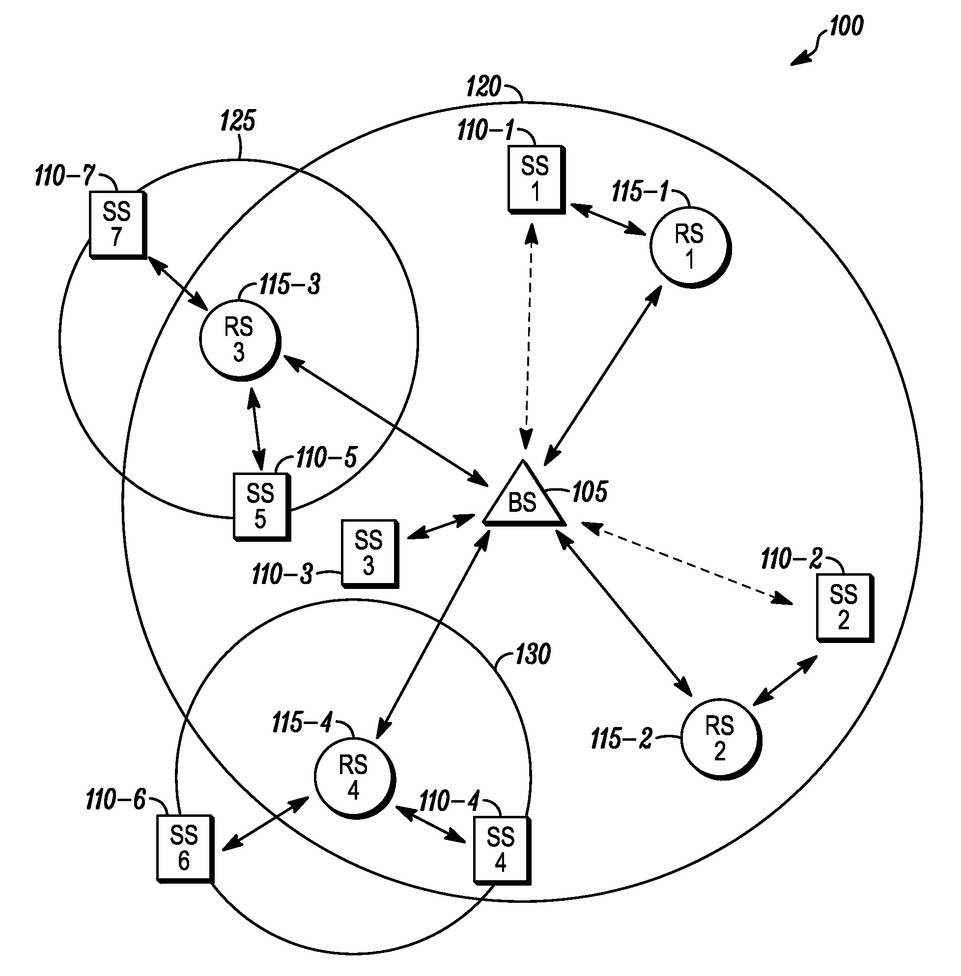
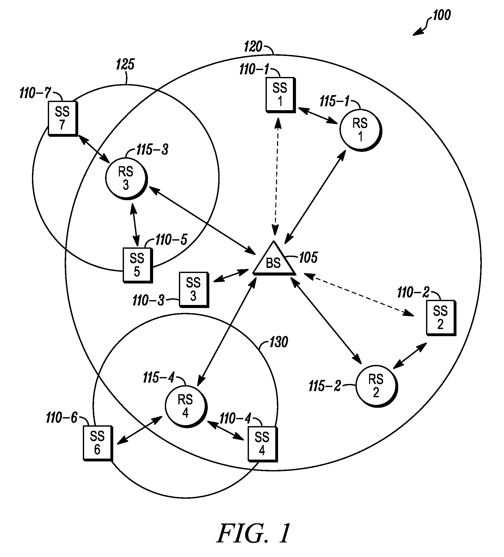
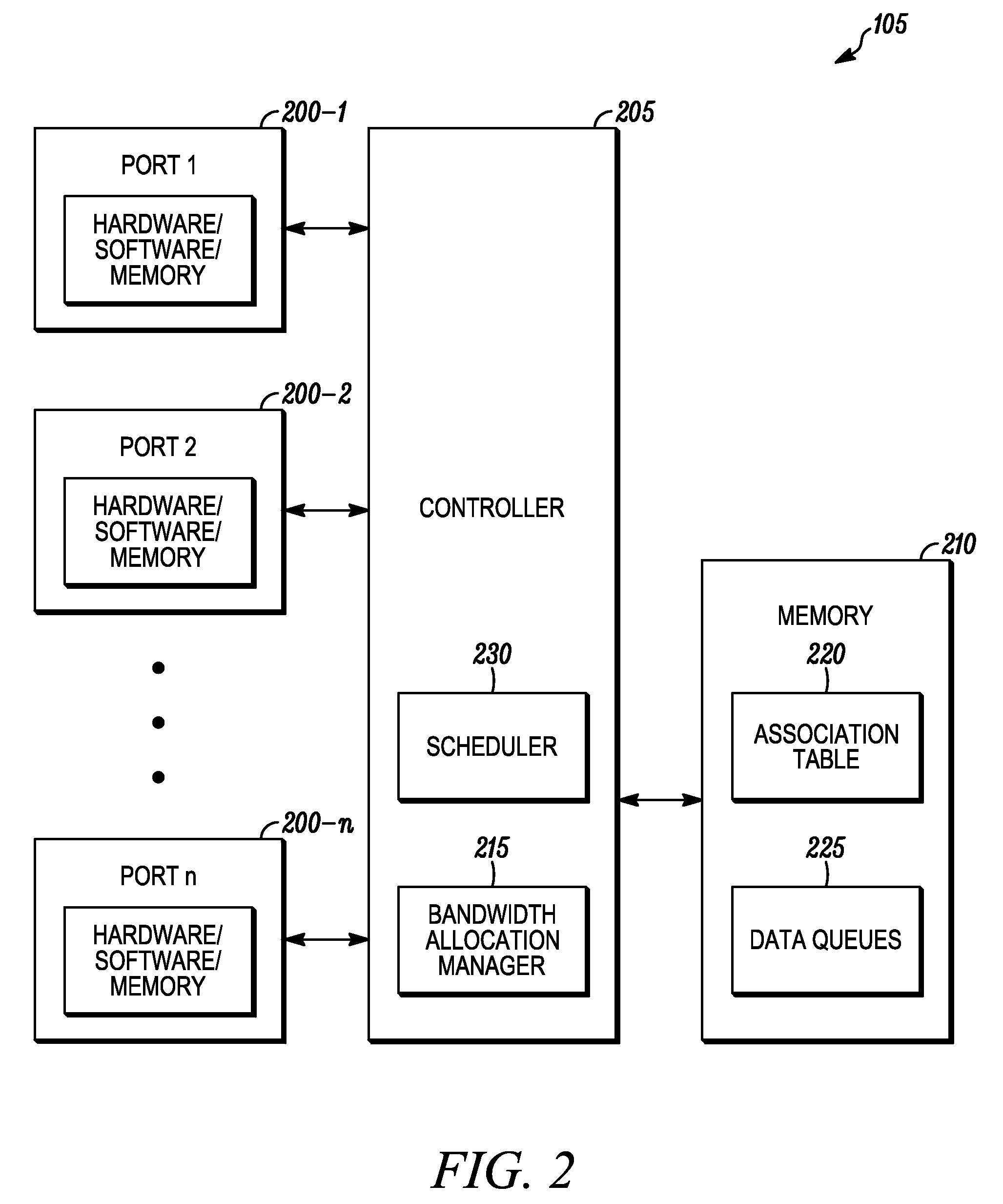
[0017]Before describing in detail embodiments that are in accordance with the present invention, it should be observed that the embodiments reside primarily in combinations of method steps and apparatus components related to relay zone bandwidth allocation in a multihop wireless communication network. Accordingly, the apparatus components and method steps have been represented where appropriate by conventional symbols in the drawings, showing only those specific details that are pertinent to understanding the embodiments of the present invention so as not to obscure the disclosure with details that will be readily apparent to those of ordinary skill in the art having the benefit of the description herein.

[0018]In this document, relational terms such as first and second, top and bottom, and the like may be used solely to distinguish one entity or action from another entity or action without necessarily requiring or implying any actual such relationship or order between such entities ...


PUM


Abstract

A method and apparatus for allocation of channel resources for relay stations operating in a multihop wireless communication system is provided for herein. The method and apparatus includes a signaling protocol between a base station scheduler and a relay station scheduler so as to achieve efficient utilization of the sector channel resources, while minimizing signaling overhead due to base station-relay station scheduler interaction.

Description

FIELD OF THE INVENTION[0001]The present invention relates generally to wireless communication systems and more particularly to the operation of a communication network utilizing relay stations.BACKGROUND[0002]An infrastructure-based wireless network typically includes a communication network with fixed and wired gateways. Many infrastructure-based wireless networks employ a mobile unit or host which communicates with a fixed base station that is coupled to a wired network. The mobile unit can move geographically while it is communicating over a wireless link to the base station. When the mobile unit moves out of range of one base station, it may connect or “handover” to a new base station and starts communicating with the wired network through the new base station.[0003]In comparison to infrastructure-based wireless networks, such as cellular networks or satellite networks, ad hoc networks are self-forming networks which can operate in the absence of any fixed infrastructure, and in...

Claims


Application Information

Patent Timeline
Patent Type & Authority Applications(United States)
IPC IPC(8): H04B7/14H04Q7/00H04W16/26H04W28/20H04W72/04H04W72/12
CPCH04B7/2606H04W16/26H04W28/20H04W88/04H04W72/0413H04W72/0453H04W84/047H04W72/0406H04W72/21H04W72/20
Inventor VISOTSKY, EUGENE
Owner ARRIS ENTERPRISES LLC
Learn More