
Conical nut

a technology of lug nuts and conical plates, which is applied in the direction of pins, fastening means, washers, etc., can solve the problems of reducing the clamp force, loosing the lug nuts on the wheels of the trailer, and creating a cumulative thickness of the stacked parts, so as to prevent the disengagement of the conical seat

Inactive Publication Date: 2008-07-10
DEXTER AXLE CO
View PDF5 Cites 34 Cited by
  • Summary
  • Abstract
  • Description
  • Claims
  • Application Information

AI Technical Summary

Benefits of technology

[0013]The invention comprises a conical nut comprising a body having a cylindrical portion, a threaded bore surface and a flange extending normally from the cylindrical portion, a biasing member comprising a disc spring, a conical seat having a tapered sur...

Problems solved by technology

A common problem encountered by freight haul tractor trailers, as well as smaller trailers used for non-commercial purposes such as recreational trailers, is the loosening of the lug nuts on the wheels of the trailer.
A common problem results from methods used to secure nuts to lug bolts on new truck and trailer wheels.
Unless properly addressed “seating-in” during initial use can result in a reduction of the clamp force, and thereby the torque, which holds the wheel to the axle hub.
Further, the stacking of components on a vehicle wheel hub creates a cumulative thickness of the stacked parts.
The initial torque can force the material of the stacked components to yield, thereby allowing the nuts to loosen by “bleeding off” the initial torque and preload, again, causing the nut to loosen.
Loss of torque can also occur as a result of long storage periods where the wheel assembly is subjected to repeated cycles of heating and cooling.
After a period of time, the lug hole diameter in the wheel can be significantly enlarged, damaging the wheel as well as severely degrading the stability of the trailer, rending it uncontrollable.
Also, relative movement of the wheel can result in fatigue failure of the lug bolts, causing catastrophic separation of the wheel from the axle hub.
For example, in an emergency or panic stop, once loosened under hard application of the brakes the wheel can shear off the lug bolts, thus rendering the trailer or vehicle uncontrollable.
Once detached the wheel can become a dangerous projectile as well, capable of seriously injuring others.

Method used


Image

  • Conical nut
  • Conical nut
  • Conical nut

Examples


Embodiment Construction

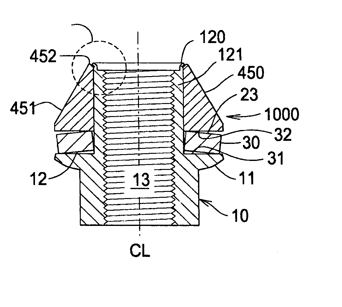
[0023]FIG. 1 is a perspective view of the conical nut. Embodiment 1000 comprises nut 10 and disc spring 30. Disc spring 30 and conical seat 450 are coaxially engaged about a shank 121.

[0024]Conical seat 450 comprises a surface 451 having a cone angle φ (FIG. 4) creating a tapered surface 451. Cone angle φ may be in the range of approximately 60° to approximately 90°. In the preferred embodiment angle φ is approximately 60°.

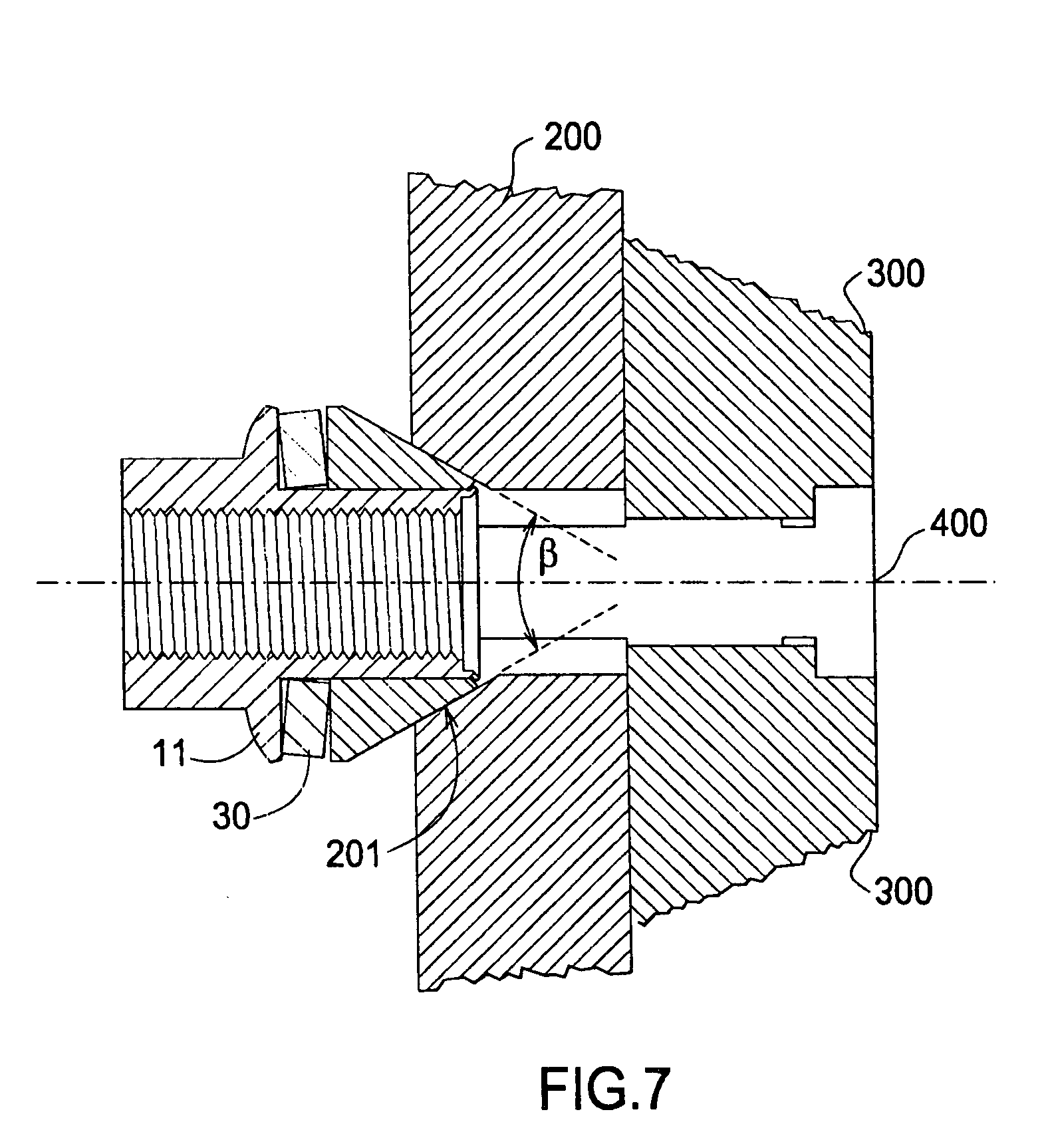
[0025]Disc spring 30 is disposed between flange 11 and conical seat 450. Disc spring 30 is also referred to as a Belleville spring, known in the art. Surfaces 12, 23 extend substantially normal to a conical nut centerline CL. In the case where disc spring 30 is present each surface 12, 23 slides upon respective surfaces 31, 32 of disc spring 30. In an alternate embodiment where disc spring 30 is not present surfaces 23 and 12 slide directly upon each other as nut 10 is torqued down on a stud.

[0026]During installation only nut 10 is rotated about stud 400. Conical ...


PUM


Abstract

A conical nut comprising a body (10) having a cylindrical portion (121), a threaded bore surface (13) and a flange (11) extending normally from the cylindrical portion, a biasing member comprising a disc spring (30), a conical seat (450) having a tapered surface (451), the conical seat coaxially engagable with the cylindrical portion, the biasing member disposed between the flange and the conical seat, and a flared rim (120) engaged with the conical seat (450) to prevent disengagement of the conical seat from the cylindrical portion.

Description

FIELD OF THE INVENTION[0001]The invention relates to a conical nut, and more particularly, to a conical wheel nut having a conical seat that is engaged with a nut by a shank rim.BACKGROUND OF THE INVENTION[0002]A common problem encountered by freight haul tractor trailers, as well as smaller trailers used for non-commercial purposes such as recreational trailers, is the loosening of the lug nuts on the wheels of the trailer.[0003]A common problem results from methods used to secure nuts to lug bolts on new truck and trailer wheels. Unless properly addressed “seating-in” during initial use can result in a reduction of the clamp force, and thereby the torque, which holds the wheel to the axle hub. This can over time create a gap between the nut and the wheel which enables the initially tight nuts to loosen up.[0004]Further, the stacking of components on a vehicle wheel hub creates a cumulative thickness of the stacked parts. The initial torque can force the material of the stacked com...

Claims


Application Information

Patent Timeline
IPC IPC(8): F16B43/00
CPCF16B37/00F16B43/00F16B41/002
Inventor DUNLAP, WILLIAM L.BARD, DANIEL W.
Owner DEXTER AXLE CO
Features
  • Generate Ideas
  • Intellectual Property
  • Life Sciences
  • Materials
  • Tech Scout
  • Unparalleled Data Quality
  • Higher Quality Content
  • 60% Fewer Hallucinations
Learn More