Sorter and roller-conveying system incorporating the sorter

a sorter and sorting technology, applied in the direction of conveyor parts, rollerways, transportation and packaging, etc., can solve the problems of reducing working efficiency, consuming time, and disadvantages of the sorting system in lifting each article, and achieve the effect of swiftly and securely sorting the articles

Inactive Publication Date: 2008-07-17
ITO DENKI KK
View PDF14 Cites 53 Cited by
  • Summary
  • Abstract
  • Description
  • Claims
  • Application Information

AI Technical Summary

Benefits of technology

[0007]According to the first form of roller-conveying system, the articles are conveyed in desired directions in a plane with no ascent or descent, thereby increasing the conveying efficiency.
[0029]In short, the present invention provides a roller-conveying system which can swiftly and securely sort the articles from one passage to another passage as desired.

Problems solved by technology

The lifting system is disadvantageous in lifting each article.
The lifting consumes time, thereby decreasing the working efficiency.
Additionally, the lifting system lacks positional flexibility.
Furthermore, the lifting system requires a large space on and around the main conveyor.
As a result, the conveying system becomes large as a whole.

Method used


Image

  • Sorter and roller-conveying system incorporating the sorter
  • Sorter and roller-conveying system incorporating the sorter
  • Sorter and roller-conveying system incorporating the sorter

Examples


Embodiment Construction

The Basic Structure of the Roller-Conveyor

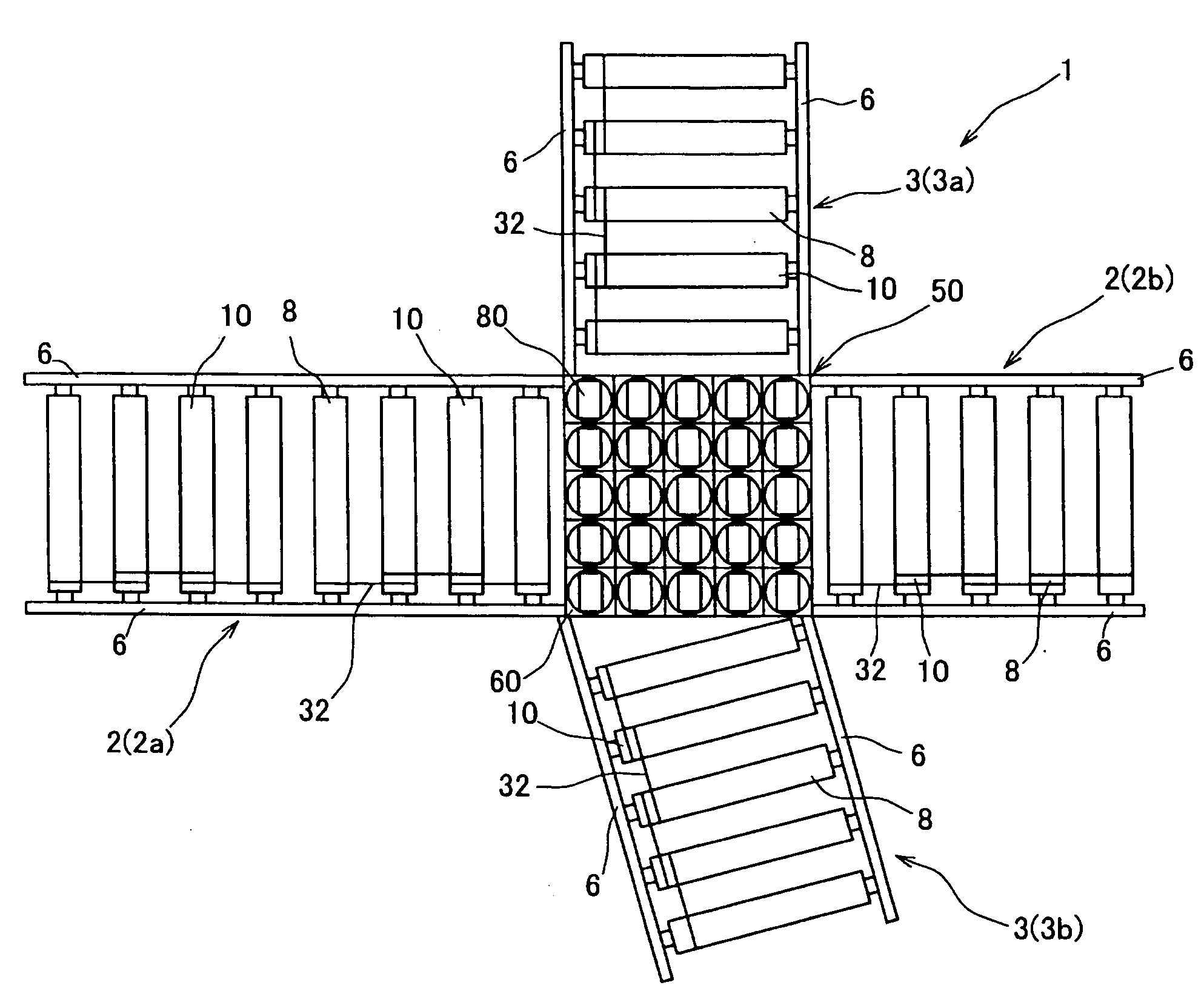
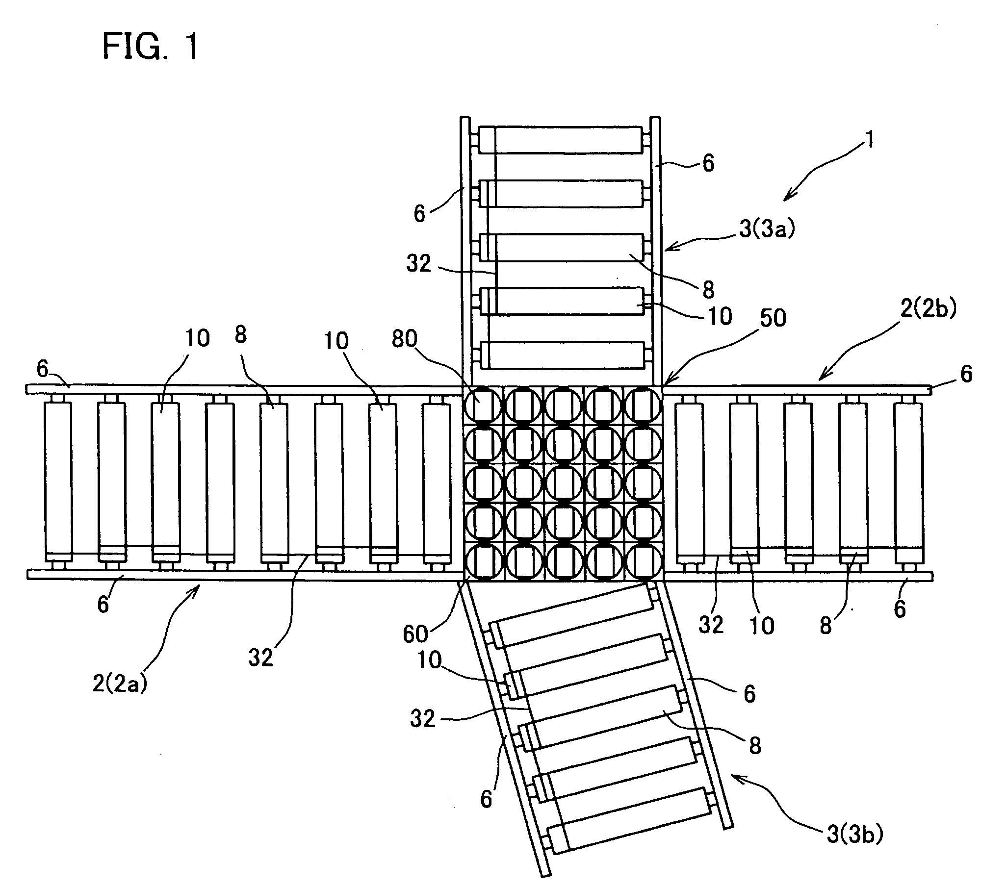
[0045]FIG. 1 shows a roller conveyer 1 having a main passage 2 and a sub-passage 3, and a sorter 50 located at the junction of the main passage 2 and the sub-passage 3.

[0046]The main passage 2 and the sub-passages 3 are constructed of two kinds of rollers; that is, free-rollers 8 and motorized rollers 10 crosswise arranged in frames 6.

[0047]The main passage 2 conveys articles, such as cartons, straightforward. The main passage 2 has two branch passages 2a at the left (upstream) and 2b at the right (downstream) of the sorter 50. The sub-passages 3 extend in different directions from the sorter 50.

[0048]The sorter 50 is designed to take over the articles from the main passage 2, and sort them in a desired direction. In the illustrated example of FIG. 1 the sub-passage 3a extends at right angle to the sorter 50, and the sub-passage 3b is arranged at a declined angle to the sorter 50.

[0049]As referred to above, each passage 2a, 2b, 3a and 3b is ...


PUM


Abstract

A roller-conveying system includes a sorter for sorting the articles from one passage to others as desired, the sorter including a plurality of cells arranged on substantially the same level as the conveying surfaces of the passages; and at least some of the cells including a motorized roller rotatably carried in a shell, and a shifter for changing the direction of the motorized roller; wherein the shifter includes a revolving shaft vertical to the conveying surface, the revolving shaft connected to the motorized roller, so as to revolve the motorized roller so as to cause it to direct toward a desired conveying passage.

Description

TECHNICAL FIELD[0001]The present invention relates generally to a roller-conveying system, and more particularly, to a roller-conveying system provided with a sorter which sorts the conveying articles in desired directions.BACKGROUND ART[0002]Japanese Patent Laid-open Specification No. 2006-44818 discloses a typical example of conventional conveying system. This system uses a lifter which lifts the conveying articles to transfer them in desired directions.[0003]The lifting system is disadvantageous in lifting each article. The lifting consumes time, thereby decreasing the working efficiency. Additionally, the lifting system lacks positional flexibility. Furthermore, the lifting system requires a large space on and around the main conveyor. As a result, the conveying system becomes large as a whole.[0004]Accordingly, the present invention is directed to a reduced size of the conveying system by providing a sorter capable of sorting on the same level as the main conveyor, thereby shif...

Claims


Application Information

Patent Timeline
Patent Type & Authority Applications(United States)
IPC IPC(8): B65G47/24
CPCB65G47/54B65G13/10
Inventor ITOH, KAZUONAKAMURA, TATSUHIKOMITSUYOSHI, MAKOTO
Owner ITO DENKI KK
Why Eureka
Try Eureka