Head removable camera

Inactive Publication Date: 2008-07-17
ELMO CO LTD
View PDF1 Cites 1 Cited by
  • Summary
  • Abstract
  • Description
  • Claims
  • Application Information

AI Technical Summary

Benefits of technology

[0010]Several types of caps are prepared in which conversion lenses are fitted respectively. One of the caps is attached to the front opening of the housing instead of the cap in which the front glass is fitted. Consequently, since a plurality of camera heads or interchangeable lenses need not be prepared, the head removable camera which is moderate in costs and economical can be provided.

Problems solved by technology

These camera heads or interchangeable l

Method used


Image

  • Head removable camera
  • Head removable camera
  • Head removable camera

Examples


Example

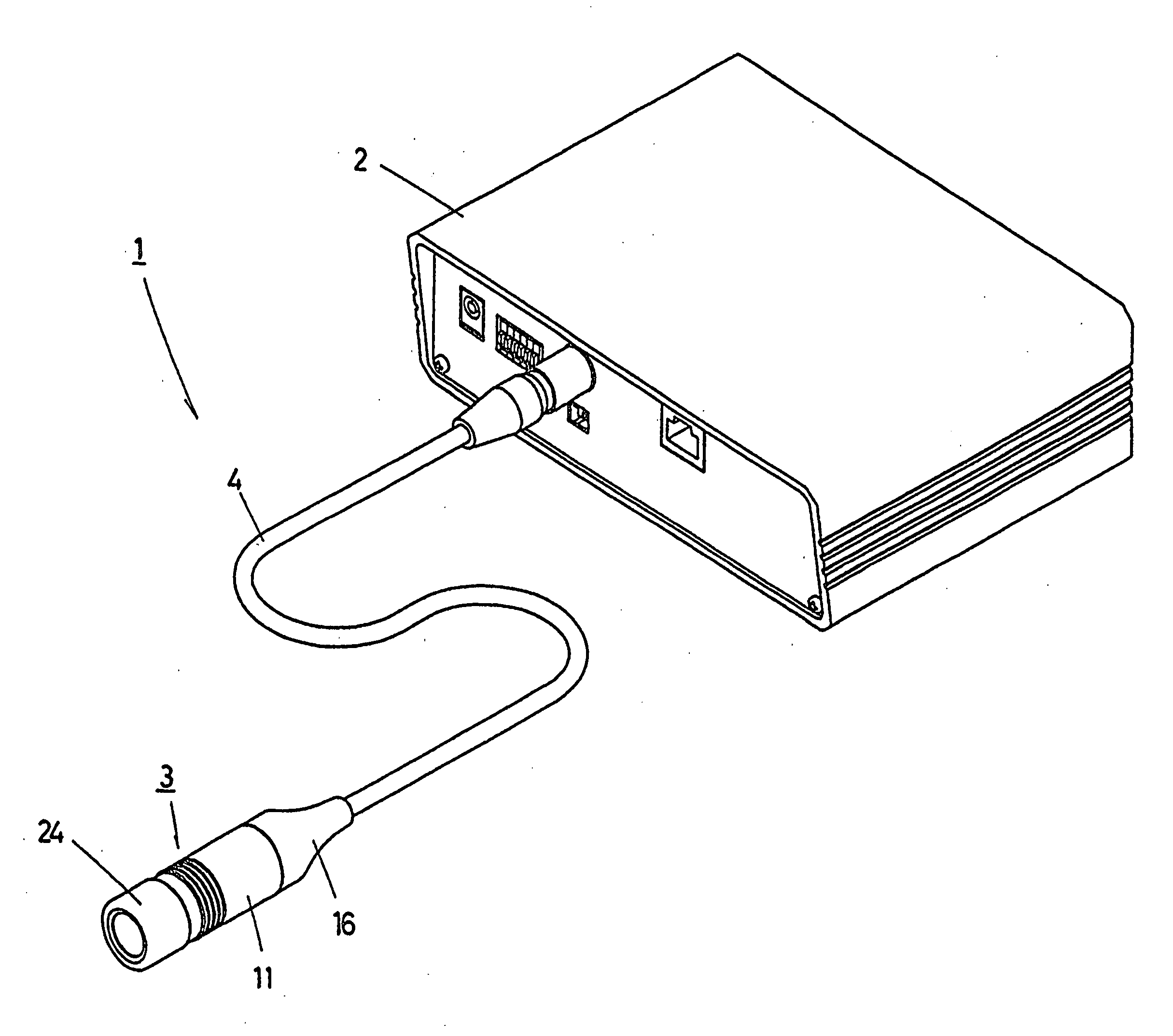
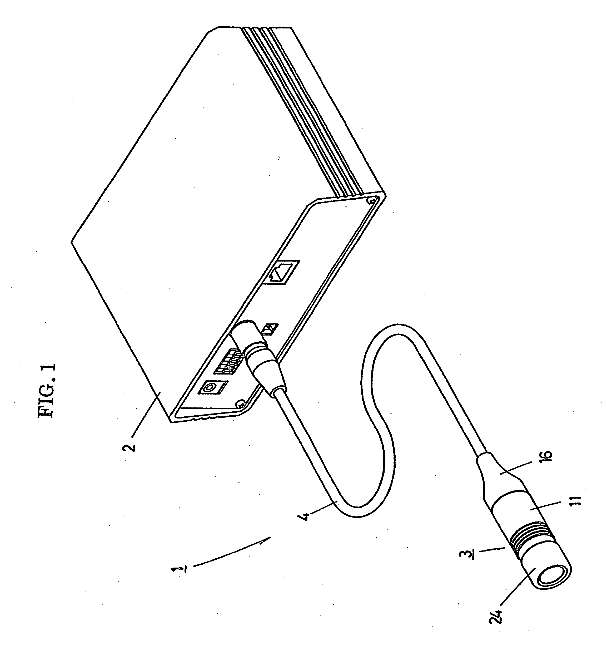
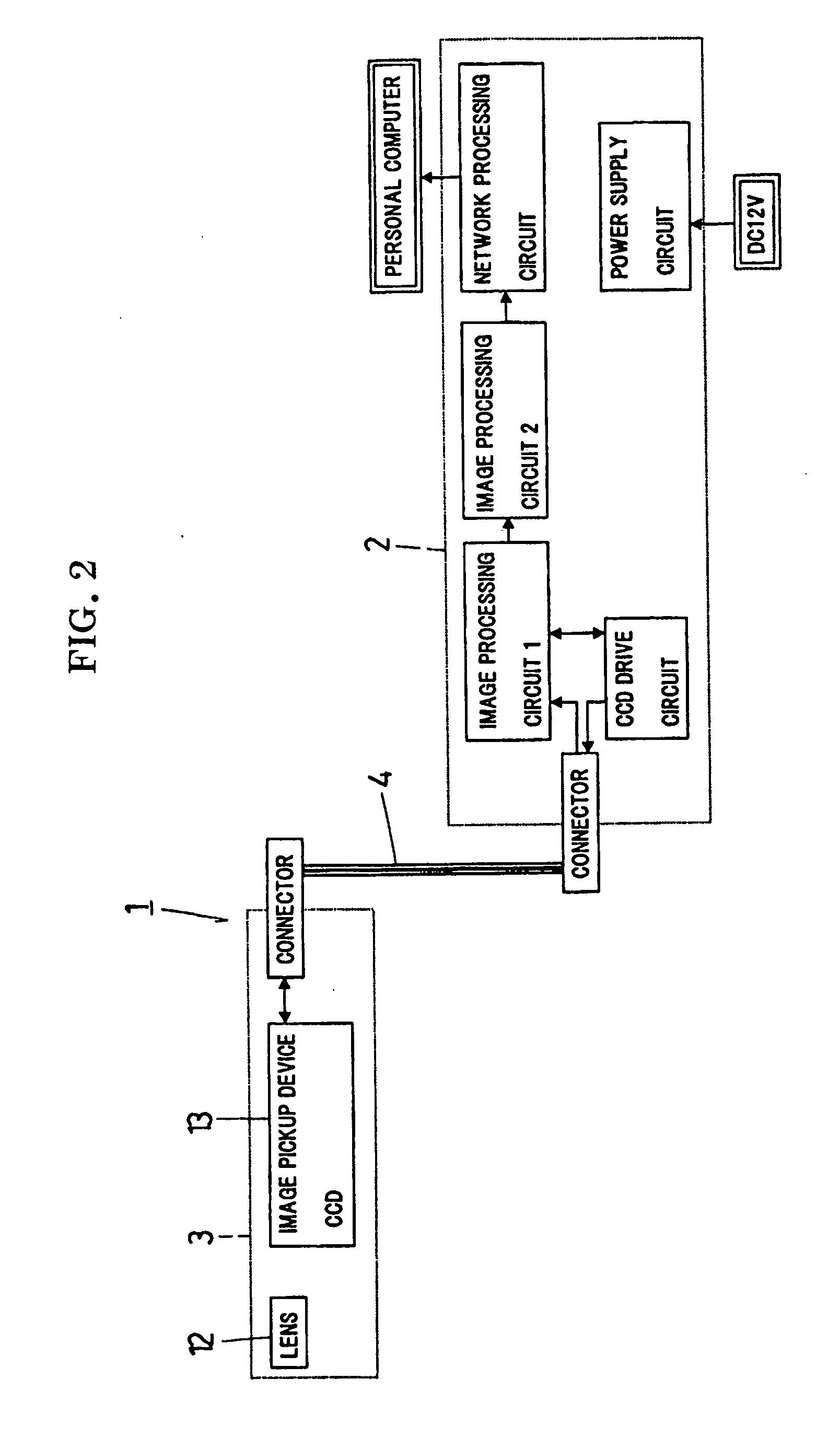
[0018]One embodiment of the present invention will be described with reference to the accompanying drawings. Referring to FIG. 1, a head removable camera 1 comprises a control unit 2 and a camera head 3. The camera head 3 includes an input / output cable (hereinafter, “cable”) 4 which connects the camera head 3 to the control unit 2. The control unit 2 includes a CCD drive circuit, image processing circuits (1) and (2) both of which processes a picture signal delivered from the CCD 13, a network processing circuit, a power supply circuit and the like.

[0019]The camera head 3 mainly comprises a housing 11, a lens unit 12, a CCD 13 and a CCD unit 14, the latter three of which are housed in the housing 11. A cable holder 15 is fixed to a rear end of the housing 11. The cable 4 is inserted through the cable holder 15 thereby to be held. A rubber sleeve 16 is fitted with an outer periphery of the rear end of the housing 11 and a part of the cable 4. The CCD unit 14 includes a board holder 1...


PUM


Abstract

A head removable camera includes a signal input/output cable having a distal end, a housing including a rear end to which the signal input/output cable is connected and a front end formed with an opening, an image pickup device housed in the housing, a lens unit housed in the housing so as to be disposed in front of the image pickup device, a first cap attached to the opening of the housing front end and including a front glass fitted therein, and a second cap in which a predetermined conversion lens is fitted, the second cap being attached to the opening of the housing front end instead of the first cap.

Description

CROSS-REFERENCE TO RELATED APPLICATIONS[0001]This application is based on and claims the benefit of priority from the prior Japanese Patent Application No. 2006-351732, filed on Dec. 27, 2006, the entire contents of which are incorporated herein by reference.BACKGROUND OF THE INVENTION[0002]1. Field of the Invention[0003]The present invention relates to a head removable camera.[0004]2. Description of the Related Art[0005]Head removable cameras have conventionally been developed which comprise a housing, an image pickup device and a lens unit latter two of which are housed in the housing. The housing has a rear end to which a distal end of a signal input / output cable is connected. The lens unit is disposed in front of the image pickup device. For example, Japanese Patent No. 3020087 discloses a head removable camera in which a camera head is housed in a waterproof casing together with a camera head housing.[0006]A several types of camera heads are prepared in order that an imaging fi...

Claims


Application Information

Patent Timeline
IPC IPC(8): H04N5/225G03B17/02G03B17/08
CPCG03B17/02H04N5/23209H04N5/2251G03B17/08H04N23/50H04N23/663H04N23/00
Inventor YAMADA, KAZUYOSHIYOSHIDA, TAKESHISHIMIZU, KEN
Owner ELMO CO LTD
Why Eureka
Try Eureka