Illumination module with similar heat and light propagation directions

a technology of illumination module and beam shaping, which is applied in the direction of lighting and heating apparatus, semiconductor devices for light sources, instruments, etc., can solve the problems of reducing the luminous flux of output light, and increasing the temperature of the substra

Active Publication Date: 2008-07-17
SIGNIFY HLDG BV
View PDF13 Cites 50 Cited by
  • Summary
  • Abstract
  • Description
  • Claims
  • Application Information

AI Technical Summary

Benefits of technology

[0016]An object of the present invention is to provide an illumination module with similar heat and light propagation directions. In accordance with one aspect of the present invention, there is provided an illumination module comprising: one or more arrays of one or more light-emitting elements for generating light; one or more heat extraction elements in thermal communication with one or more arrays, said one or more heat extraction elements transferring heat in substantially a first direction; and an optical system optically coupled to the array, the optical system configured to direct the light from the light-emitting elements substantially in the first direction.

Problems solved by technology

However, for solid-state luminaries having LEDs, the thermal energy from the LEDs is transferred to the substrate, causing an increase in temperature and the LEDs to function less optimally resulting in a reduction in the luminous flux of the output light.
However, increases in the drive current causes a further temperature increase in the substrate, thereby compounding the negative impact of the thermal energy on the performance of the solid-state illumination module.
Often the size and positioning of the thermal management system in a luminaire restricts the space available for beam shaping optics, which can reduce the quality of coloured light mixing and beam collimation.
In this set-up, the heat travels away from the source either perpendicularly to the light emitted by the source, or in the opposite direction to that of the light emitted by the source, wherein both of these configurations can result in a bulky arrangement.
A drawback associated with the loop heat pipe of Huang is that the cover becomes bulky and has to adopt the shape of the loop heat pipe.
Use of such a loop heat pipe may require a complicated arrangement which may restrict the design of the illumination apparatus and may increase costs.
In this LED lamp, the heat pipe is generally positioned opposite to the light emitting side of the light source, which may result in an elongated configuration of the LED lamp.
As a result, this arrangement for a lighting apparatus may not be practical due to the requirement of a larger volume as more LED chips are being used, which can result in a bulky lighting apparatus.
This configuration of an optoelectronic device would therefore result in a diminished luminous flux output therefrom.
In addition the versatility of design of an optoelectronic device of this configuration is limited by the required configuration of the heat pipe.
In addition, the lighting apparatus as proposed by Ono et al. can be complex and can include a plurality of mechanical parts, which can again lead to a bulky lighting apparatus.
The lamp post as defined by Martin et al, is configured such that light and heat travel in opposite directions thereby resulting in an inefficient use of space.

Method used


Image

  • Illumination module with similar heat and light propagation directions
  • Illumination module with similar heat and light propagation directions
  • Illumination module with similar heat and light propagation directions

Examples


example 1

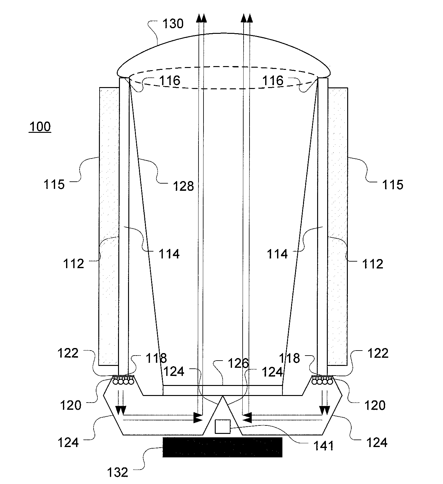
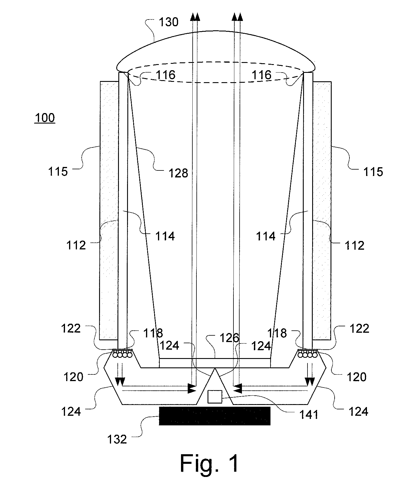
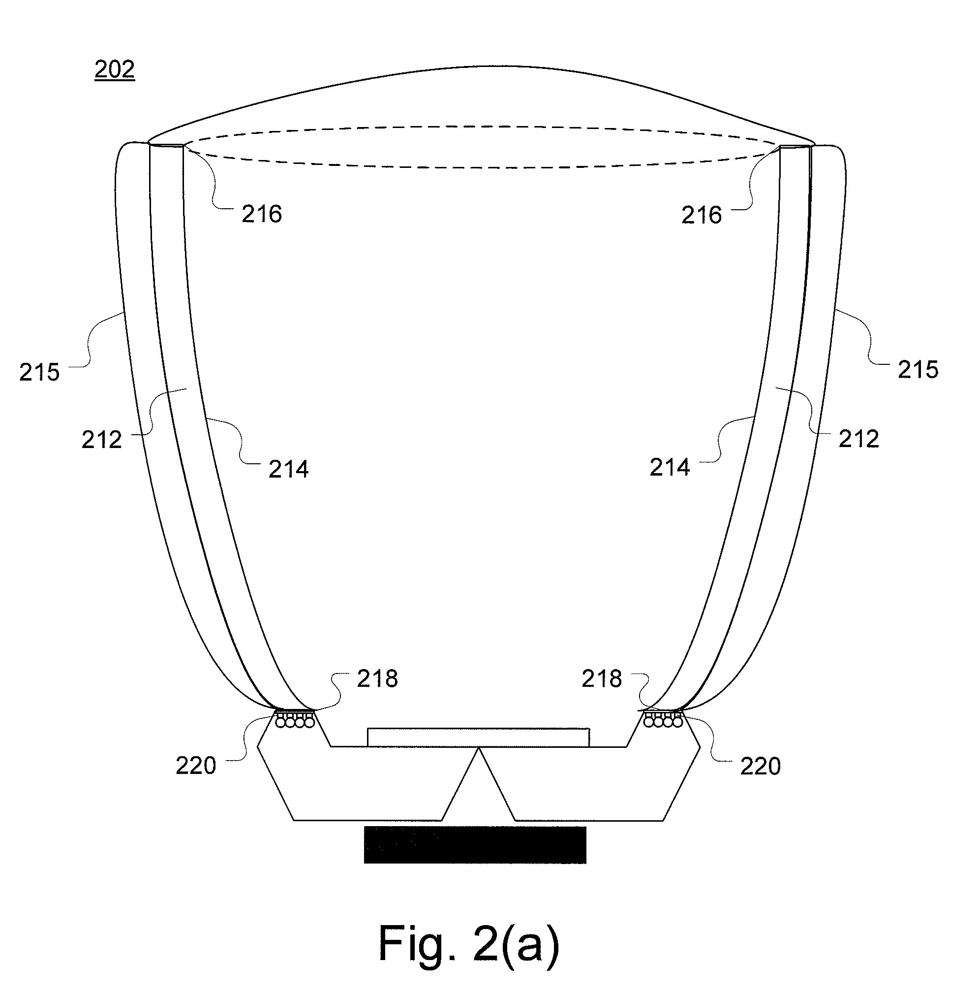
[0086]Referring now to FIG. 2(a) which illustrates an illumination module according to one embodiment of the present invention. The illumination module 202 includes heat pipes 212 for cooling a plurality of light-emitting elements 220. The heat pipes 212 each include an intermediate bulk portion 214, a condenser region at one end 216 of the bulk portion 214 including an adjacent portion thereof and a evaporator region 218 at an opposite end of the bulk portion 214. The bulk portions 214 of the heat pipes 212 have reflective sidewall portions. The reflective sidewall portions of the bulk portions 214 also have parabolic cross-sections so as to form an optical element for beam shaping of the output light from the light-emitting elements 220. It can be appreciated by those skilled in the art that the shape of the sidewall portions of the bulk portions may be concave, elliptical, circular, or other shapes depending on the beam shaping requirements of the illumination module 200.

[0087]Th...

example 2

[0088]FIG. 3(a) illustrates an illumination module 302 according to one embodiment of the present invention. The illumination module 302 includes a plurality of heat pipes 312 having contact surfaces 318 in thermal communication with corresponding side-mounted light-emitting elements 320. A possible benefit of side mounting the light-emitting elements is that fewer reflections are needed for light extraction. Optical reflectors 324 or light guides are positioned along the path of the output light from the light-emitting elements 320 so as to bend the output light emanating from the light-emitting elements 320 in a direction along a longitudinal axis of the illumination module 302. Inside the envelope defined by the illumination module, and for the majority of the length of the illumination module, heat and light from the light-emitting elements both travel in substantially the same direction.

[0089]FIG. 3(b) illustrates one embodiment of the present invention similar to that illustra...

example 3

[0090]One embodiment of the present invention is shown in FIG. 4. Illumination module 400 includes heat pipes 412 and a plurality of light-emitting elements 420 grouped into arrays. Each array of light-emitting elements 420 is attached to the evaporator end of each heat pipe 412 and is thermally connected to the respective heat pipe 412 for transfer of heat from the light-emitting elements 420 to the heat pipes 412. The illumination module 400 also includes a tandem lens array 430 and 431 located at the entrance and aperture ends of the illumination module 400 to manipulate the optical characteristics of the output light.


PUM


Abstract

The present invention provides an illumination module comprising one or more light-emitting elements which are thermally coupled to one or more heat extraction elements. The one or more heat extraction elements are configured to transfer heat in substantially a first direction. One or more optical elements are further integrated into the illumination module, wherein the one or more optical elements are optically coupled to the one or more light-emitting elements and configured to redirect the light emitted by the one or more light-emitting elements in substantially the first direction.

Description

FIELD OF THE INVENTION[0001]The present invention pertains to thermal management and beam shaping of illumination devices, and more particularly to an illumination device having a heat extraction element for thermal management of one or more light sources.BACKGROUND[0002]High brightness illumination modules are used in a number of lighting applications, such as ambient lighting, accent lighting, wall washing, signage, advertising, decorative and display lighting, façade lighting, custom lighting and the like. These illumination modules typically include a plurality of light sources, such as incandescent bulbs, fluorescent tubes, neon, or solid-state light-emitting diodes (LEDs), coupled to a power management system to supply and control the intensity of the light sources depending on the brightness requirements of the lighting application.[0003]While in operation, most high brightness illumination modules generate excess amounts of thermal energy. In the case of incandescent bulbs, ...

Claims


Application Information

Patent Timeline
Patent Type & Authority Applications(United States)
IPC IPC(8): F21V33/00
CPCF21V7/0008F21V13/04F21V29/004F21Y2101/02G02B7/008G02B19/0028F21V29/71F21V29/745F21V29/75F21V29/76G02B19/0066F21V29/006F21Y2115/10F21V29/51F21V29/74
Inventor SPEIER, INGOLOVELAND, DAMIEN
Owner SIGNIFY HLDG BV
Why Eureka
Try Eureka