
Sound transmitting device

Inactive Publication Date: 2008-07-17
MICROSONIC
View PDF8 Cites 10 Cited by
  • Summary
  • Abstract
  • Description
  • Claims
  • Application Information

AI Technical Summary

Benefits of technology

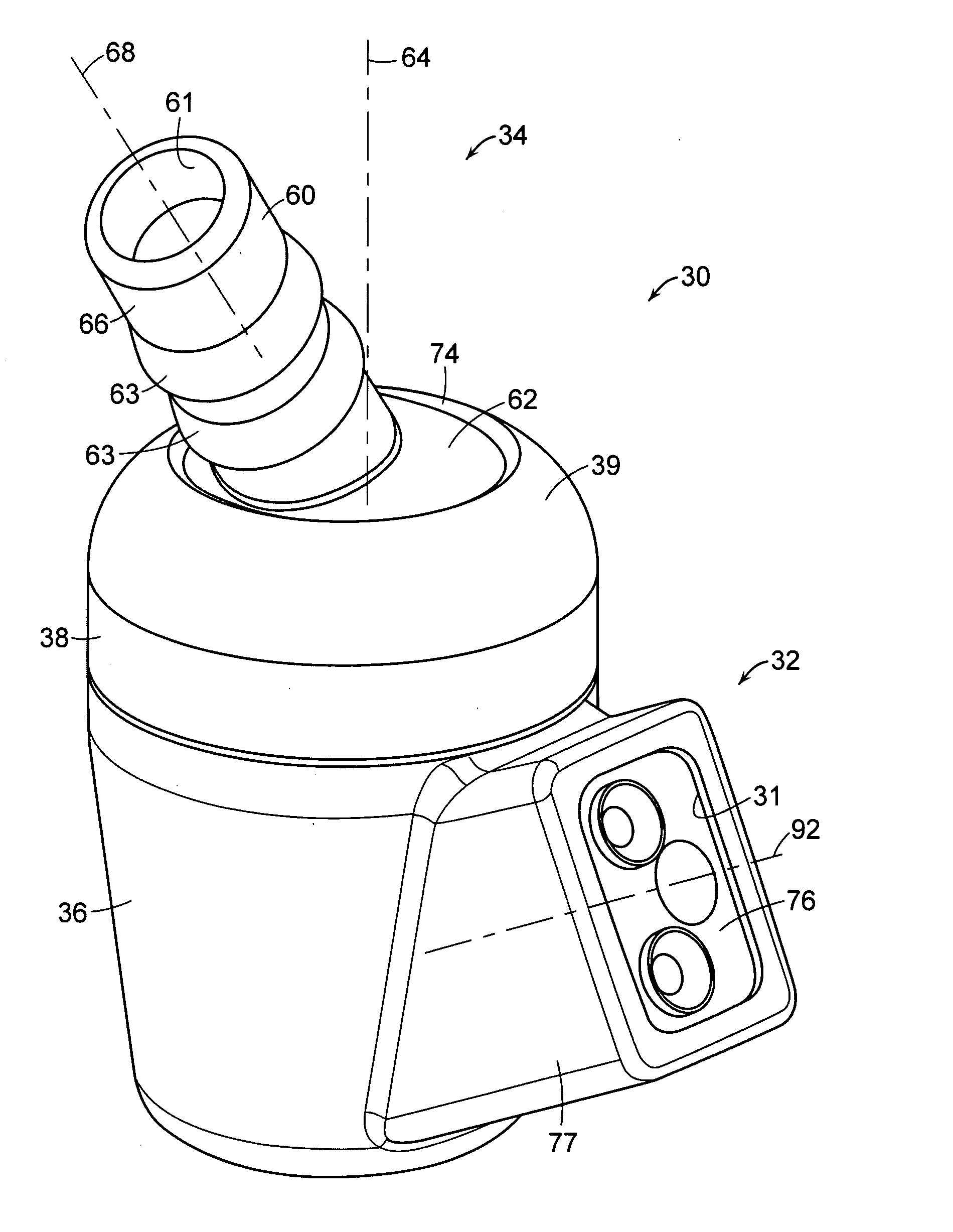
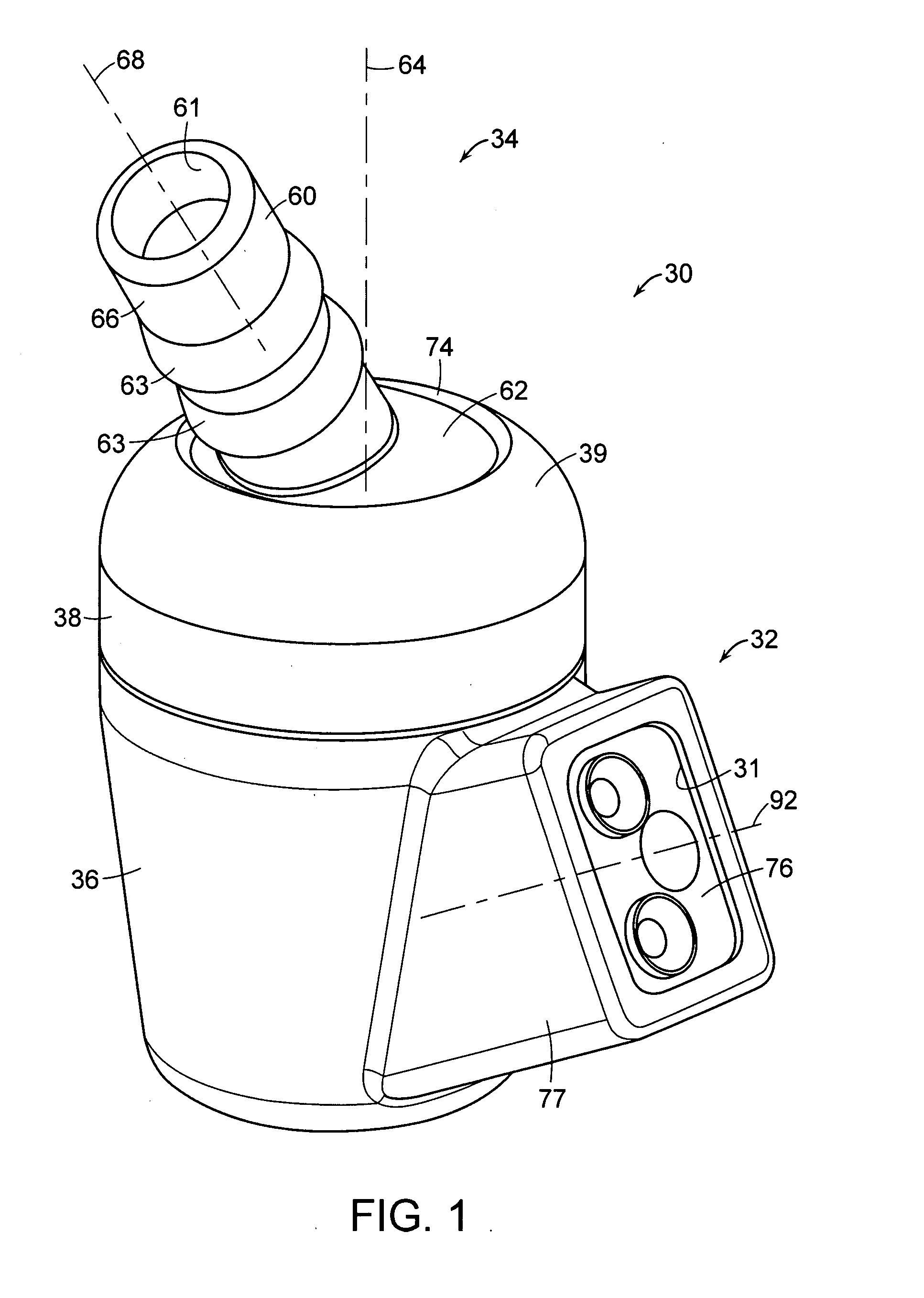
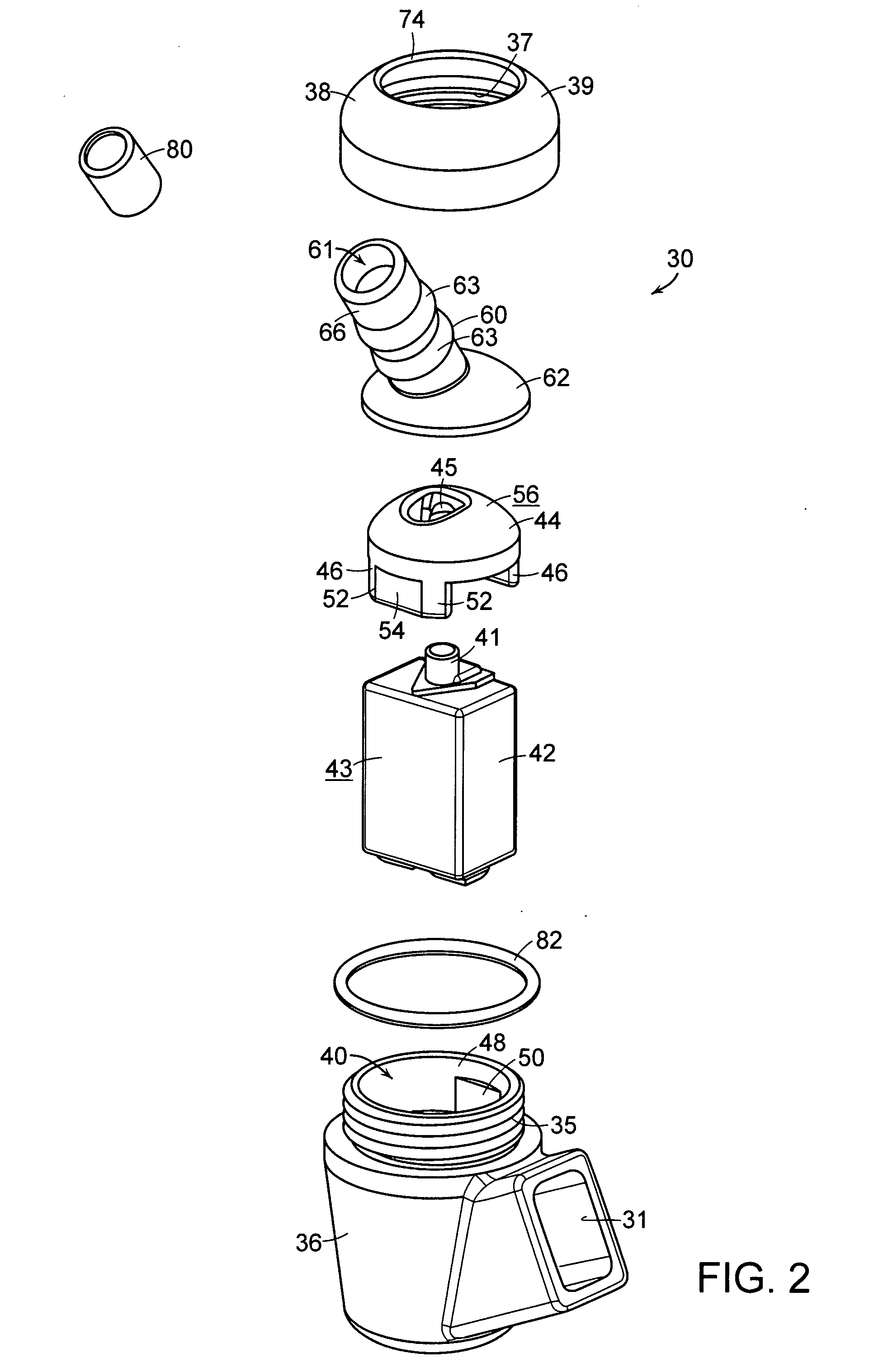
[0007]In various embodiments, the present invention includes a sound transmitting device configured to fit within an ear canal, such as a hearing aid or a monitor, for example, having first and second portions which are relatively movable with respect to each other. As a result of these relatively moving portions, the device can better accommodate changes in the shape and / or orientation of the ear canal. More particularly, after the device has been fitted into the ear canal, the first and second portions can move relative to each other and comply with a new shape and / or orientation of the ear canal. As a result, it is less likely that the device will impede the change in the ear canal thereby reducing potential discomfort to the user. To facilitate this relative movement, in various embodiments, the first portion can include a first partially spherical surface and the second portion can include a second partially spherical surface, wherein the first and second surfaces are configured to permit relative movement therebetween. In at least one embodiment, such relative movement includes relative rotational movement between the first and second portions about more than one axis.

Problems solved by technology

However, owing to such a snug fit, it is often difficult to remove the housing from the ear canal.
In some circumstances, this may damage the wires and / or the connection between the wires and the housing.
As a result, these housings, while comfortable to the user in some circumstances, can be uncomfortable to the user in other circumstances.
More particularly, although the housings may fit comfortably when initially fitted within a person's ear canal, the shape, and / or orientation, of their ear canal can change causing discomfort to the user when the housing obstructs such a change.
However, such materials can quickly lose their elasticity or can become soiled.
Accordingly, these previous devices are often a nuisance.

Method used


Image

  • Sound transmitting device
  • Sound transmitting device
  • Sound transmitting device

Examples


Embodiment Construction

[0028]Sound transmitting devices, including hearing aids and monitors, for example, can be used to amplify, or otherwise control, the presentation of sound waves into a person's ear. For example, hearing aids can be used to receive sound waves, amplify the sound waves, and transmit the amplified sound waves into the ear of a person who may be hearing impaired, for example. In at least one embodiment, the hearing aid can be configured to only amplify sound waves having particular frequencies. For example, in various embodiments, the hearing aid can include an aperture extending therethrough which is tuned to amplify a specific range of frequencies. In at least one embodiment, the aperture can be tuned via the selection of the length and diameter of the aperture.

[0029]In various embodiments, the hearing aid can include a transducer for receiving electrical signals, or impulses, transmitted thereto and for generating sound waves which correspond to the electrical impulses in a predeter...


PUM


Abstract

A sound transmitting device configured to fit within an ear canal, such as a hearing aid or a monitor, for example, having first and second portions which are relatively movable with respect to each other. As a result of these relatively moving portions, the device can better accommodate changes in the shape and / or orientation of the ear canal. More particularly, after the device has been fitted into the ear canal, the first and second portions can move relative to each other and comply with a new shape and / or orientation of the ear canal. As a result, it is less likely that the device will impede the change in the ear canal thereby reducing potential discomfort to the user. To facilitate this relative movement, the first and second portions can include at least partially spherical surfaces which are configured to permit relative movement therebetween.

Description

BACKGROUND[0001]1. Field of the Invention[0002]The present invention generally relates to hearing aids, monitors, and other sound transmitting devices, and, more particularly, to improvements thereof which facilitate their fit within and removal from an ear canal.[0003]2. Description of the Related Art[0004]As known in the art, hearing aids, monitors, and other sound transmitting devices, can be used to improve, and protect, a person's hearing. More particularly, these devices can be used to amplify, or otherwise control, the presentation of sound waves into a person's ear, for example. Previous devices have included housings, and transducers positioned therein, which are configured to be positioned within the ear, to receive electrical signals, or impulses, and convert these electrical impulses into to sound waves. In the past, these devices have included either custom housings, i.e., housings which are intended to fit within a particular person's ear, or universal housings, i.e., ...

Claims


Application Information

Patent Timeline
IPC IPC(8): H04R1/02
CPCH04R25/60H04R2225/41H04R25/658H04R25/656H04R25/604
Inventor MAJOR, MIKLOS
Owner MICROSONIC
Learn More