
Method to generate an output audio signal from two or more input audio signals

a technology of audio signal and output signal, applied in the direction of transducer circuit, transducer casing/cabinet/support, electrical transducer, etc., can solve the problems of inconvenient application, and inability to achieve beamforming for getting a signal with a higher directional response, so as to achieve low signal to noise ratio and signal quality. the effect of low

Inactive Publication Date: 2008-07-17
ILLUSONIC
View PDF2 Cites 27 Cited by
  • Summary
  • Abstract
  • Description
  • Claims
  • Application Information

AI Technical Summary

Benefits of technology

"The invention proposes a technique for improving the directionality of microphones or signals with an associated directional response, in order to enable better stereo or surround recording using coincident or nearly coincident microphones. This is achieved by using adaptive signal processing applied to a plurality of microphone signals or other signals with an associated directionality. The invention addresses limitations of conventional beamforming and is suitable for applications where a time-invariant beamshape is required. The technical effect is improved directionality and better quality music recording."

Problems solved by technology

The directionality of microphones is often not high enough, resulting in compromised music recording.
Beamforming for getting a signal with a higher directional response is limited due to spatial aliasing, dependence of beamwidth on frequency, and a requirement of a high number of microphones.
Adaptive beamforming is suitable for applications where the only aim is to optimize signal to noise ratio, but not suitable for applications where a time-invariant beamshape is required.

Method used


Image

  • Method to generate an output audio signal from two or more input audio signals
  • Method to generate an output audio signal from two or more input audio signals
  • Method to generate an output audio signal from two or more input audio signals

Examples


Embodiment Construction

[0031]The detailed description is organized as follows. Section I motivates the proposed scheme and presents a few examples on what it achieves. The proposed processing is described in detail in Section II, using the example of three input signals. The directionality corresponding to the processed output signal for directional sound is derived in Section III. Section IV discusses the corresponding directionality for diffuse sound. Considerations for the case of mixed sound, i.e. directional and diffuse sound, reaching the microphones, are discussed in Section V. Use of the proposed technique for B-Format / Ambisonic decoding is described in Section VI. Section VII discusses different cases than three input signals, the consideration of directional responses in three dimensions, and other generalizations.

I. MOTIVATION AND EXAMPLES

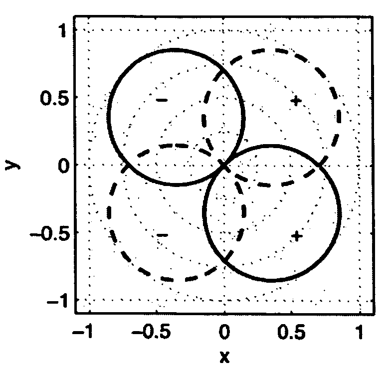
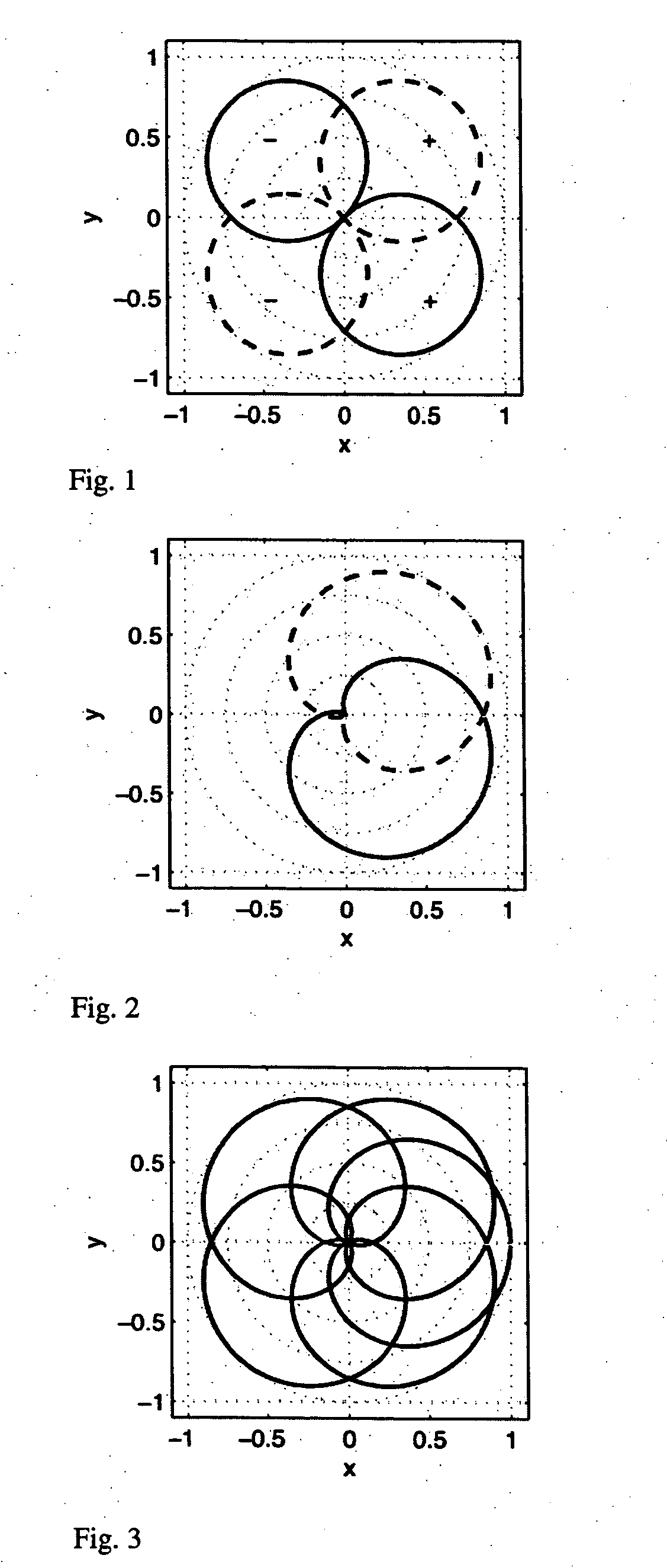
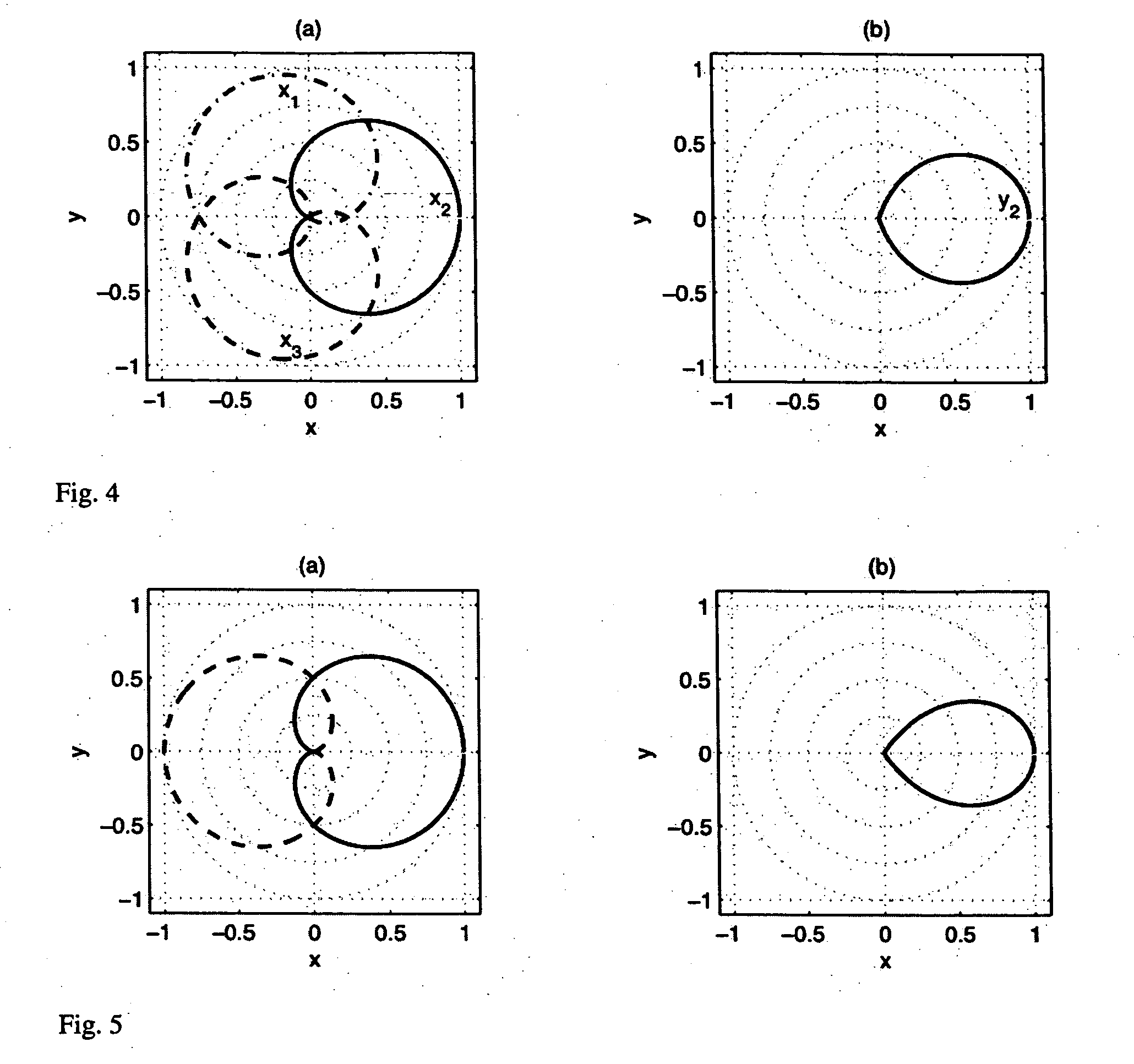
[0032]The responses of a coincident pair of dipole microphones, as often used for stereo recording, are illustrated in FIG. 1. This microphone configuration d...


PUM


Abstract

The directionality of microphones is often not high enough, resulting in compromised music recording. Beamforming for getting a signal with a higher directional response is limited due to spatial aliasing, dependence of beamwidth on frequency, and a requirement of a high number of microphones. Adaptive beamforming is suitable for applications where the only aim is to optimize signal to noise ratio, but not suitable for applications where a time-invariant beamshape is required. The invention addresses these limitations, using adaptive signal processing applied to a plurality of microphone signals or other signals with an associated directionality.A method is therefore proposed to generate an output audio signal y from two or more input audio signals (x1, x2, . . . ), this method comprising the steps of:define one input signal as reference signalfor each of the other input signals compute gain factors related to how much of the input signal is contained in the reference signaladjust the gain factors using a limiting functioncompute the output signal by subtracting from the reference signal the other input signals multiplied by the corresponding adjusted gain factors

Description

INTRODUCTION[0001]The invention relates to microphones and directional responses of microphones. A plurality of microphone signals, or other signals with associated directional response, are processed to overcome the limitation of low directionality of microphones.BACKGROUND ART[0002]Many techniques for stereo recording have been proposed. The original stereo recording technique, proposed by Blumlein in the 1930's, uses two dipole (figure of eight) microphones pointing towards directions +45 degrees relative to the forward direction. Blumlein proposed the use of “coincident” microphones, that is, ideally the two microphones are placed at the same point. In practice, coincident microphone techniques place the microphones as closely together as practically possible, i.e. within a few centimeters.[0003]Alternatively, one can use a coincident pair of microphones with other directionality for stereo recording, such as two cardioid microphones. Two cardioids have the advantage that sound ...

Claims


Application Information

Patent Timeline
Patent Type & Authority Applications(United States)
IPC IPC(8): H04R3/00
CPCH04R3/005
Inventor FALLER, CHRISTOF
Owner ILLUSONIC
Learn More