
Apparatus and method for visible light communication

a technology of visible light and communication apparatus, applied in the direction of electrical apparatus, electromagnetic transmission, close-range type systems, etc., can solve the problem that the original function of the illumination function of the transmitted light is los

Active Publication Date: 2008-07-17
SAMSUNG ELECTRONICS CO LTD
View PDF2 Cites 33 Cited by
  • Summary
  • Abstract
  • Description
  • Claims
  • Application Information

AI Technical Summary

Benefits of technology

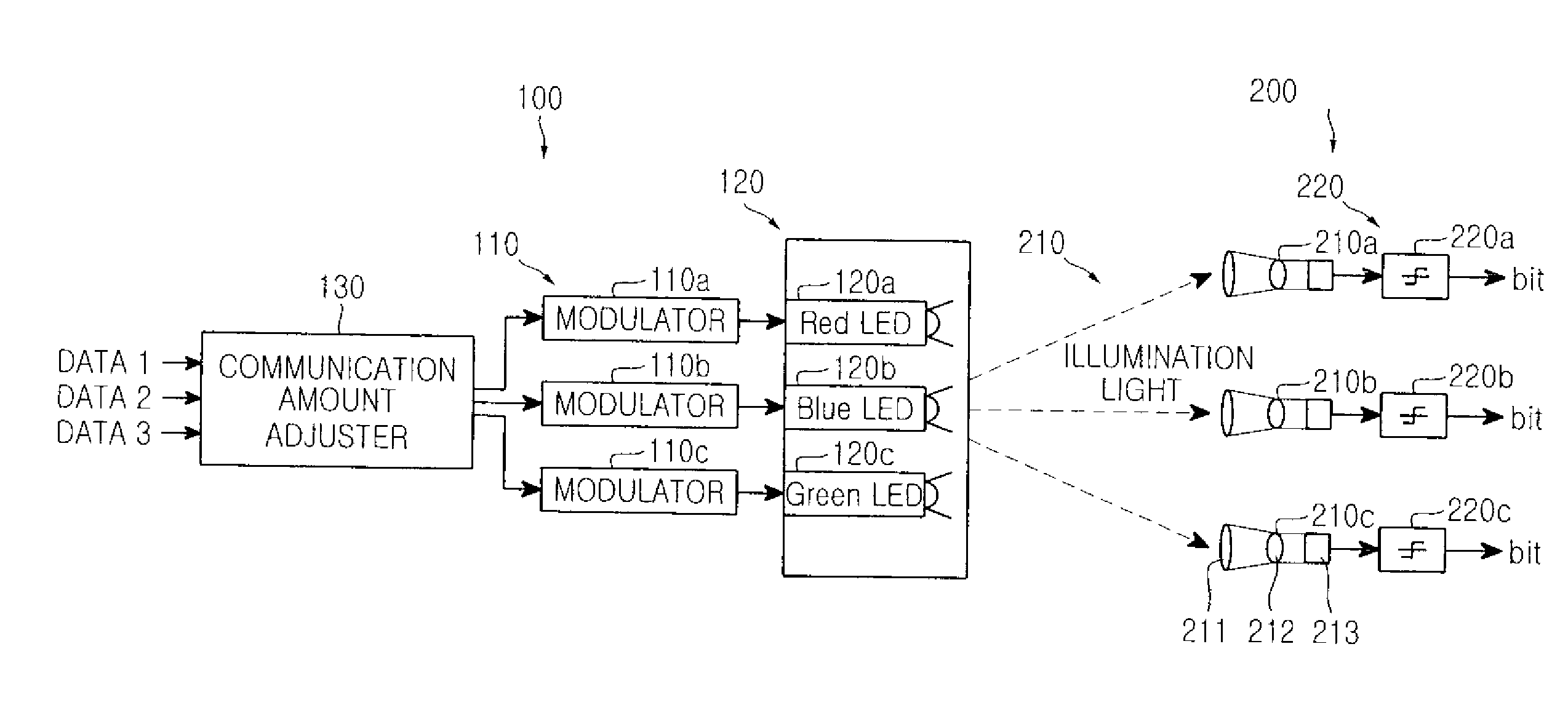
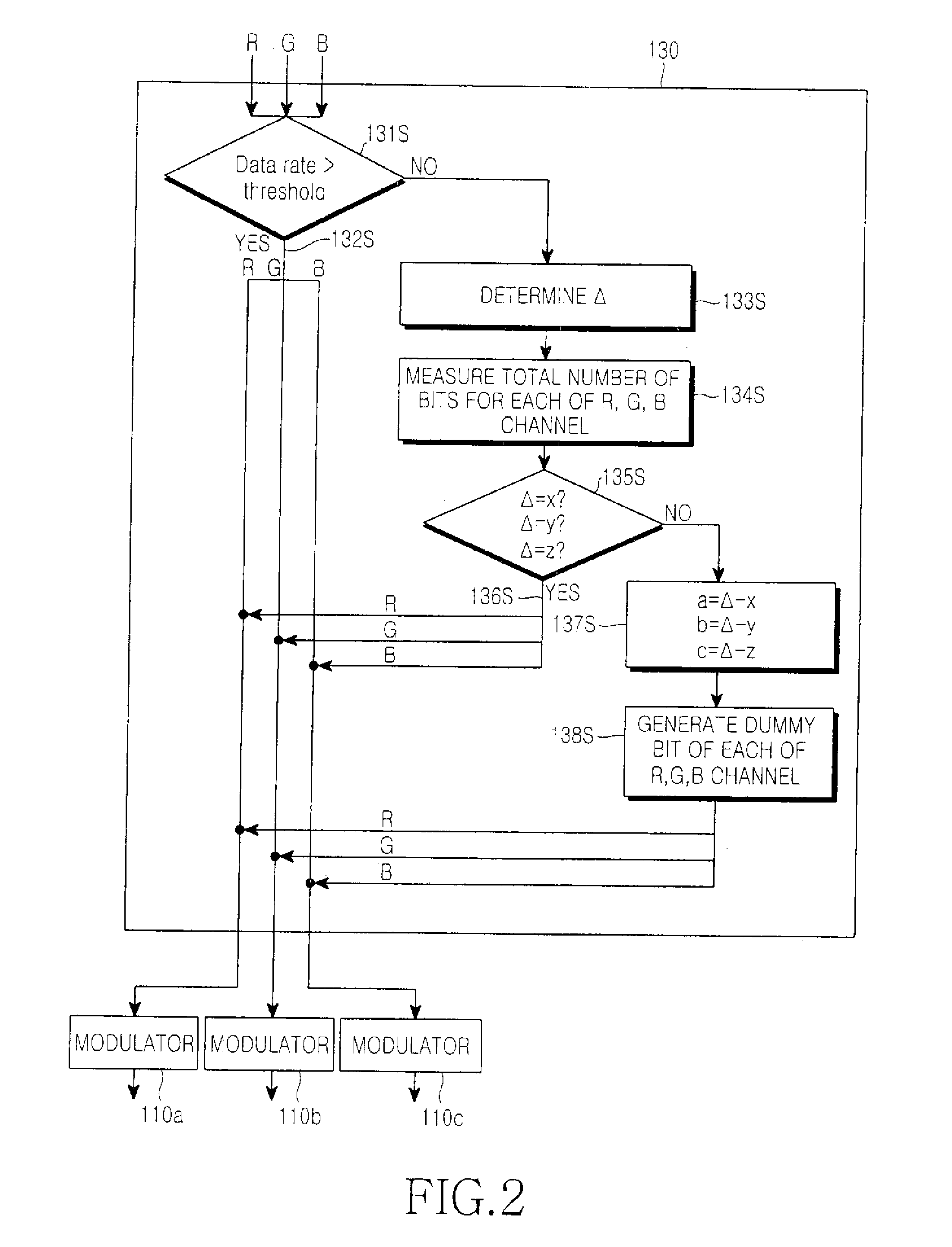
[0011]In accordance with another embodiment of the present invention, there is provided a visible light communication method for transmitting a plurality of communication data signals by using an illuminator including a plurality of individual light sources as a plurality of channels, the visible light communication method including the steps of: (1) adjusting a communication amount by adding a dummy data to each channel of the plurality so that each input data to be transmitted by using the plurality of individual light sources as the plurality of channels has an equal communication amount; and (2) modulating data of each channel having the added dummy data and providing the modulated data as driving signals of the plurality of individual light sources, so that the illuminator can emit white light.

Problems solved by technology

However, when channels of R, G, and B convey data having different lengths, white light is not emitted even through concentration of three lights of R, G, and B. As a result, the transmitted lights lose their original function for illumination.

Method used


Image

  • Apparatus and method for visible light communication
  • Apparatus and method for visible light communication
  • Apparatus and method for visible light communication

Examples


Embodiment Construction

[0017]Hereinafter, an exemplary embodiment of the present invention is described with reference to the accompanying drawings. For the purposes of clarity and simplicity, a detailed description of known functions and configurations incorporated herein is omitted as it may make the subject matter of the present invention rather unclear.

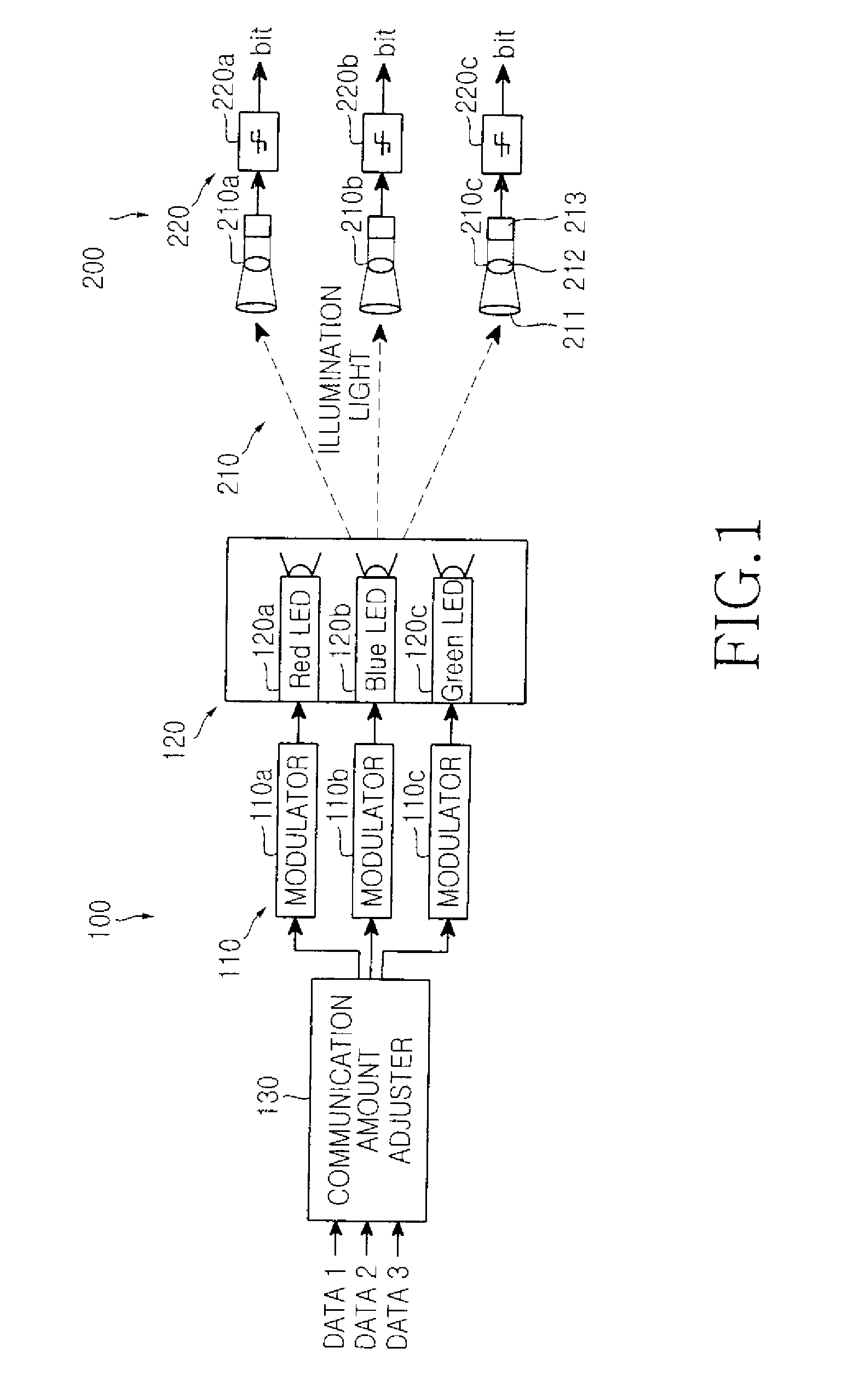
[0018]FIG. 1 is a block diagram illustrating a construction of an apparatus for visible light communication according to an exemplary embodiment of the present invention.

[0019]Referring to FIG. 1, the apparatus for visible light communication includes a transmitting side device 100 and a reception side device 200. Herein, the transmitting side device 100 includes a modulator 110, an illuminator 120, and a communication amount adjuster 130. Herein, the reception side device 200 includes a photoelectric converter 210 and a demodulator 220.

[0020]The modulator 110 modulates input data (data 1, data 2, and data 3) according to a scheme such as an On / Off Key ...


PUM


Abstract

Disclosed are an apparatus and a method for visible light communication, which apparatus uses an illuminator equipped with a plurality of light sources, so that the apparatus can be used for illumination, as well as for visible light communication. The visible light communication apparatus includes an illuminator for generation of the illumination light, the illuminator including a plurality of light sources with luminescence center wavelengths on mutually different visible regions; a communication amount adjuster for receipt of the plurality of communication data signals, and generation of each dummy data so that data to be transmitted through each of the plurality of LEDs has an equal communication amount; and a modulator for receipt of the plurality of communication data signals and their corresponding dummy data, and modulation of the received communication data signals and their corresponding received dummy data into driving signals for a plurality of LEDs configured as a light source.

Description

CLAIM OF PRIORITY[0001]This application claims the benefit under 35 U.S.C. §119(a) of an application entitled “Apparatus and Method for Visible Light Communication,” filed in the Korean Intellectual Property Office on Jan. 15, 2007 and assigned Serial No. 2007-4243, the entire contents of which are hereby incorporated by reference.BACKGROUND OF THE INVENTION[0002]1. Field of the Invention[0003]The present invention relates to an apparatus for visible light communication and a method for visible light communication using the same, and more particularly to an apparatus and a method for visible light communication using a Light Emitting Diode (LED) light source which emits visible light.[0004]2. Description of the Related Art[0005]A visible light communication apparatus refers to a system for wirelessly transmitting data by means of LED-based lamps such as an interior / exterior illumination lamp, a signboard lamp, a traffic light, a road lamp, etc. Such a visible light communication app...

Claims


Application Information

Patent Timeline
IPC IPC(8): H04B10/00
CPCH04B10/116H04B10/1141H04B10/00
Inventor WON, EUN-TAESON, JAE-SEUNG
Owner SAMSUNG ELECTRONICS CO LTD
Learn More