Utility lighter

a technology of utility lighters and lighters, applied in the field of utility lighters, can solve the problems of inconvenience for the flame of the conventional utility lighter is vulnerable to wind, and the inconvenience of the user of the conventional utility lighter

Inactive Publication Date: 2008-07-17
YANG JOHN
View PDF20 Cites 17 Cited by
  • Summary
  • Abstract
  • Description
  • Claims
  • Application Information

AI Technical Summary

Benefits of technology

[0010]A main object of the present invention is to provide a utility lighter which is capable of igniting a torch flame at a distance from the lighter casing.
[0011]Another object of the present invention is to provide a utility lighter comprising a bendable extension arm which is capable of conducting piezoelectricity from a piezoelectric unit to an upper end portion of the bendable extension arm so as to assist production of the torch flame at a torch nozzle. In other words, the inherent physical nature of the utility lighter of the present invention assists its operation.
[0012]Another object of the present invention is to provide a utility lighter comprising a heat insulating arrangement which is capable of substantially preventing the high temperature from transmitting to the user's hand even after extended ignition (e.g. ignition for around ten seconds) of the torch flame.
[0013]Another object of the present invention is to provide a utility lighter comprising a safety arrangement for preventing accidental ignition of the torch flame.
[0014]Another object of the present invention is to provide a utility lighter which is capable of preventing unwanted residual ignition when the user stops igniting the utility lighter. Thus, the present invention aims to maintain maximum safety for the user.
[0015]Another object of the present invention is to provide a utility lighter which does not involve complicated or expensive mechanical components so as to minimize the manufacturing cost of the present invention.

Problems solved by technology

There exist several disadvantages in relation to this kind of conventional utility lighter.
First, the lighter flame produce by the conventional utility lighter is vulnerable to wind.
Unfortunately, however, utility lighters are frequently used in outdoor environment.
Thus, when the utility lighter is used in a windy environment, the flame may go out very frequently and this presents an inconvenience scenario for the user of the conventional utility lighter.
Although this may solve the particular problem at hands, there may well be circumstances that this solution cannot work at all.
For example, when the users need to use the utility lighter in a confined area, he or she may not be able to turn the lighter casing very conveniently.
Second, instead of using a utility lighter, the user may use a torch (a windproof) lighter for igniting the target object.
However, the problem for this particular solution is that for conventional windproof lighters, the flame ignition nozzle is so close to the lighter casing that the user may not be able or desire to place the lighter casing at that position.
Third, since the distance between the ignition nozzle and the gas releasing valve of conventional utility lighter is fairly long, there exists the possibility that when the user stops igniting the lighter, residual gas retained within the gas tube connecting the gas releasing valve and the ignition nozzle will continuously flow out from the gas tube via the ignition nozzle.
For most of the conventional windproof lighters, they have not been designed to support prolonged ignition.
Thus, there is little, if any, measure which has been employed to prevent the high temperature of the torch flame from transmitting to the users' hands and the respective lighter casing.
As a result, although in many circumstances, a torch flame is preferred, the conventional mechanical structure of conventional windproof lighters is such that the user may not wish to use them for their specific purposes.

Method used


Image

  • Utility lighter
  • Utility lighter
  • Utility lighter

Examples


Embodiment Construction

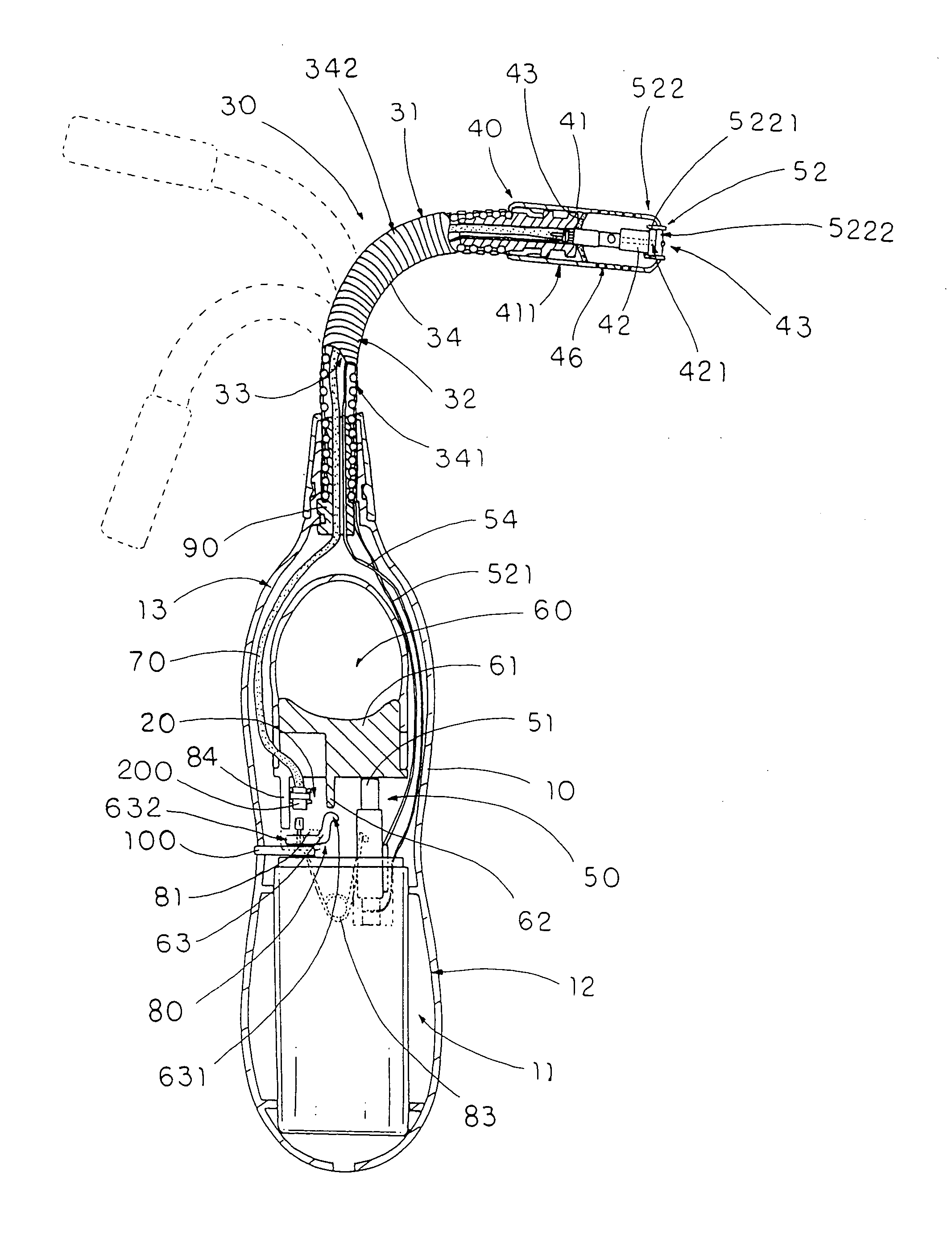
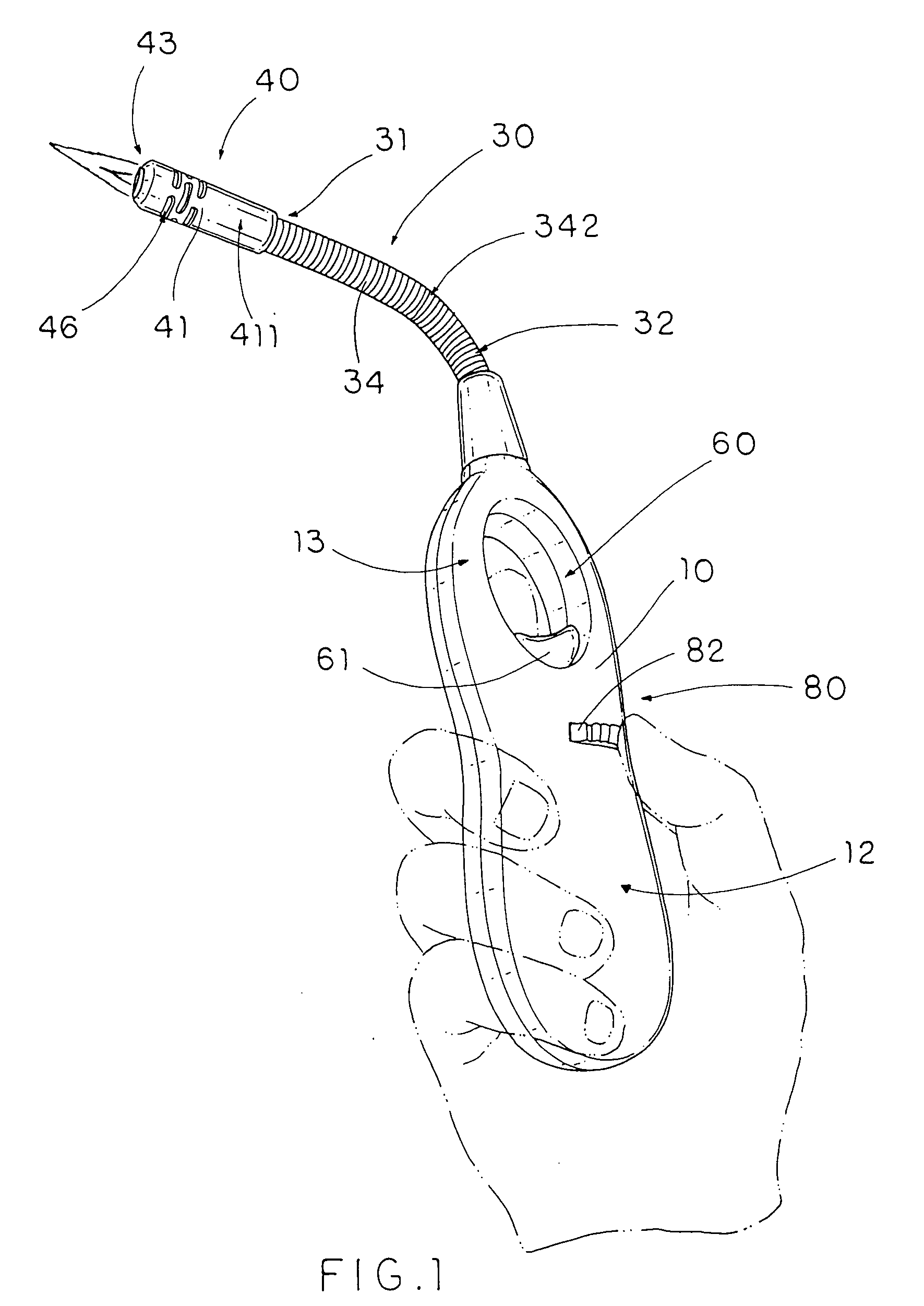
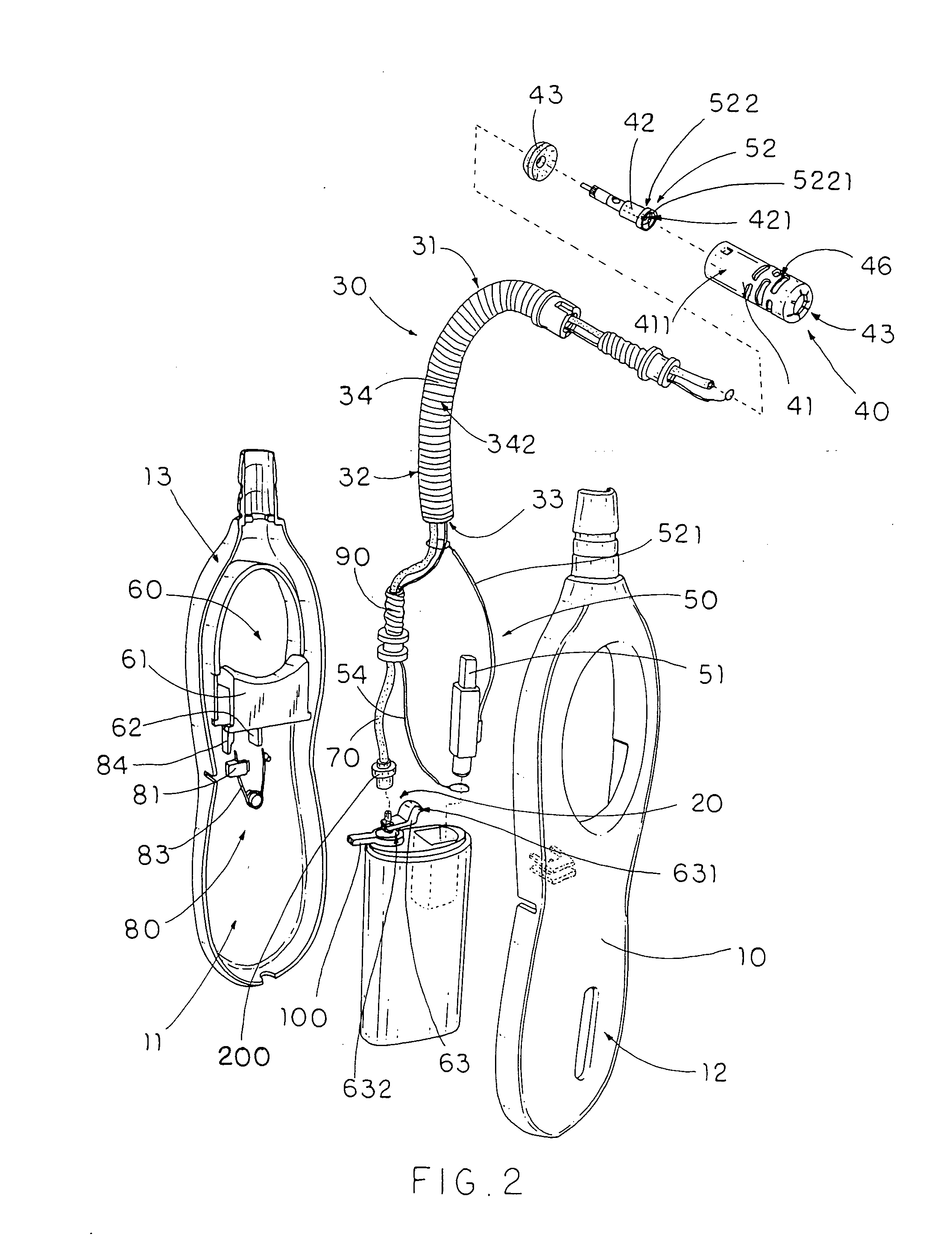
[0030]Referring to FIG. 1 to FIG. 4 of the drawings, a utility lighter, such as a barbecue lighter, according to a preferred embodiment of the present invention is illustrated, in which the utility lighter comprises a handle casing 10, a gas releasing valve 20, a bendable extension arm 30, a torch nozzle 40, a piezoelectric unit 50, and an actuation device 60. The handle casing 10 has a fuel storage compartment 11 formed therein for storing a predetermined amount of liquefied gas. The gas releasing valve 20 is provided at the fuel storage compartment 11 for releasing the gas therein in a controllable manner when the gas releasing valve 20 is uplifted.

[0031]The bendable extension arm 30 has an upper end 31 and a lower end 32 extended from the handle casing 10, wherein the bendable extension arm 30 has a deformable receiving channel 33 which is extended from the lower end 32 to the upper end 31 and is adapted to be curved when the extension arm 30 is selectively bent between the upper...


PUM


Abstract

A utility lighter includes a handle casing, a gas releasing valve, a bendable extension arm, a torch nozzle, a piezoelectric unit and an actuation device. The bendable extension arm has an upper end and a lower end extended from the handle casing, wherein the extension arm has a deformable receiving channel which is extended from the lower end to the upper end and is adapted to be curved when the extension arm is selectively bent between the upper end and the lower end. The torch nozzle is provided at the upper end of the extension arm to communicate with the gas releasing valve through the receiving channel for releasing the gas through the torch nozzle when the actuation device is actuated to depress the piezoelectric unit. The result is that a torch flame is generated at the torch nozzle at a distance from the handle casing.

Description

BACKGROUND OF THE PRESENT INVENTION[0001]1. Field of Invention[0002]The present invention relates to a lighter, and more particularly to a utility lighter which is capable of igniting a torch flame at a distance from the lighter casing.[0003]2. Description of Related Arts[0004]A conventional utility lighter comprises a lighter casing having a fuel storage chamber for storing a predetermined amount of liquefied gas, a gas releasing valve communicated with the fuel storage chamber for releasing the liquefied gas when the gas releasing valve is uplifted, a flexible extension tube extended between the lighter casing and the ignition nozzle, an ignition nozzle provided at the top end portion of the extension tube, a piezoelectric unit, and an actuation button. The piezoelectric unit comprises a main body, a depressible part movably extended from the main body, and a spark generating tip extended from the main body to the ignition nozzle via the flexible extension tube, in such a manner t...

Claims


Application Information

Patent Timeline
Patent Type & Authority Applications(United States)
IPC IPC(8): F23Q7/06F23D14/28F23D14/46
CPCF23Q3/002F23Q2/167
Inventor YANG, JOHN
Owner YANG JOHN
Why Eureka
Try Eureka